
Ultrasonic insect repellent circuit

The circuit is designed to generate high-frequency ultrasonic waves that target the auditory systems of common household pests. The piezoelectric speaker, designated as BLD, is crucial in converting the electrical signal from the circuit into sound waves that are inaudible to humans but disruptive to pests. The output from the first base circuit pin is critical; it initiates the pulse generation that drives the speaker.
The modulation circuit is built around a 555 timer, configured in astable mode, allowing it to produce a continuous pulse train. The frequency of the output signal can be adjusted by varying the resistance and capacitance in the circuit, enabling a range of frequencies from 32 kHz to 62 kHz. This frequency modulation is essential for effectively disrupting the behavior of pests, as different species may respond to different frequencies.
The design also incorporates a transformer to step up the voltage of the AC signal from the power supply, ensuring that the piezoelectric speaker receives sufficient power to produce the desired ultrasonic output. The use of a transformer not only amplifies the signal but also isolates the circuit from the AC mains, enhancing safety and reliability.
The overall effectiveness of the device in pest control relies on its ability to cover a substantial area. With a range of up to 1,600 square feet, it is suitable for various indoor environments. The continuous operation of the device is designed to create an uncomfortable environment for pests, leading to their gradual disappearance. In larger spaces, deploying multiple units can ensure comprehensive coverage and improve results.
In conclusion, this ultrasonic pest repeller circuit effectively utilizes electrical pulses and piezoelectric technology to create a hostile environment for common household pests, leveraging frequency modulation to enhance its efficacy across a wide area.Electrical pulses generated by the first base circuit pin output, and then sent through R6 piezoelectric speaker BLD, switched to the electric pulse ultrasonic waves to space r adiation. Sweep principle of the circuit is very simple, use the transformer secondary voltage AC signal to the modulation circuit 555 feet, to reach the purpose of changing the pulse frequency, the frequency range of 32kHz ~ 62kHz. According to foreign information described, the device can use more, you can get rid of rats, cockroaches, fleas, the effective area of up to 1 6rr12.
As long as the device is placed in the room, turned on the power, continuous working, rats, cockroaches, fleas will decrease with time, can be reached within three months, get rid of the above pests purpose indoor mouse will not appear, cockroaches and fleas. If the housing area is large, can put a few in the room can be,
Related Circuits

This is a white LED lamp that activates when the telephone rings. The cool white light aids in locating the phone in low-light conditions and assists in managing clutter. The circuit for the white LED lamp that illuminates upon a...
This is a variable power supply controlled by a PIC microcontroller. An LCD display is included in the circuit to show the actual output voltage and current values. A push-button switch is used to adjust the output voltage and...
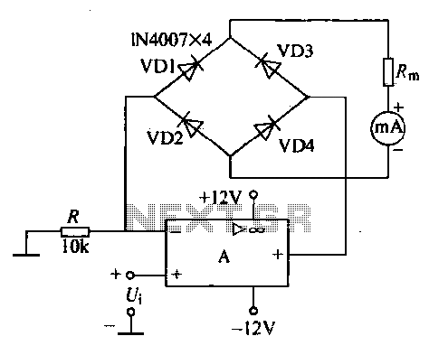
An operational amplifier, a diode bridge rectifier, and DC mA AC voltmeter tables are illustrated in the figure. The operational amplifier used is the LM324. The measured AC voltage is applied to the inverting terminal of the operational amplifier,...
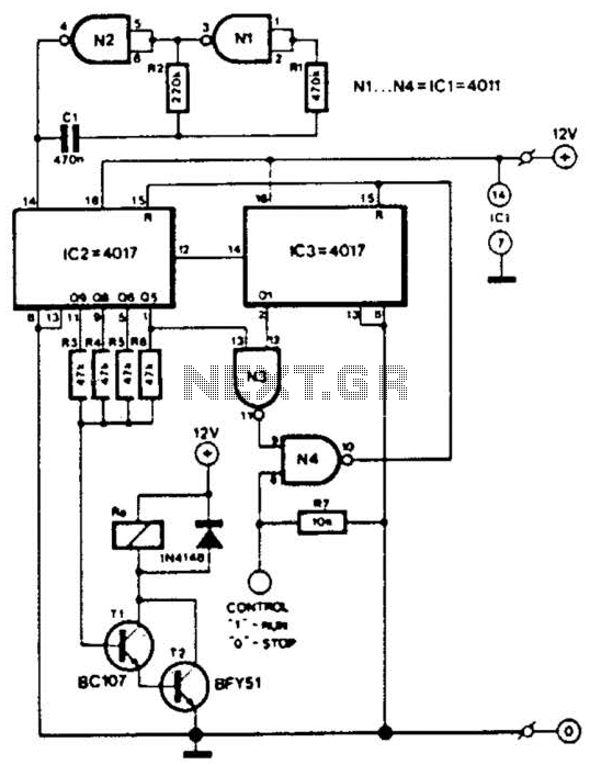
This circuit is designed for a small private telephone installation. The ringing tone sequence consists of 400 ms on, 200 ms off, 400 ms on, and 2 ms off. In the accompanying diagram, N1 and N2 create an oscillator...
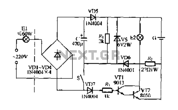
Figure 283 illustrates a blackout emergency lighting controller designed for straightforward external installation with two leads. This controller can directly replace the P Chan Tong Ge opening. Under normal power conditions, it functions like a conventional switch to control...
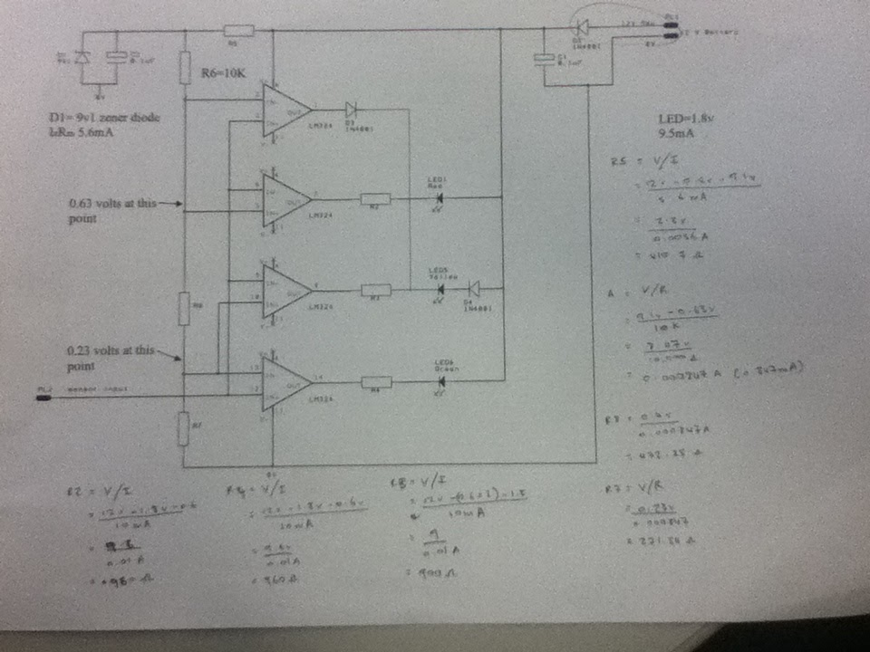
The diagram illustrates the connections for the inputs and outputs of each operational amplifier from the power source, detailing how each operational amplifier is configured to operate individual light-emitting diodes (LEDs). It also includes calculations for determining each resistor...