
AC voltmeter circuit

The circuit comprises an LM324 operational amplifier configured in an inverting amplifier setup. The input AC voltage is connected to the inverting terminal, while the non-inverting terminal is grounded. The high input impedance of the LM324 ensures minimal loading on the input source, allowing for accurate voltage measurements without significant signal degradation. The feedback loop incorporates a diode bridge rectifier, which serves to convert the AC input into a DC output.
The diode bridge consists of four diodes arranged in a bridge configuration, allowing for full-wave rectification. This arrangement enables the circuit to handle both halves of the AC waveform, resulting in a smoother DC output. The operational amplifier's feedback path includes these diodes, which helps to counteract the non-linear behavior typically exhibited by diodes in rectifier circuits.
The output current from the bridge rectifier, which is the rectified version of the input AC voltage, is expressed as the input voltage divided by the resistance in the feedback loop. This relationship indicates that the output current is independent of the non-linear characteristics of the diodes, thus providing a more stable and reliable measurement.
The average voltage measured at the output is directly proportional to the input AC voltage, making the circuit suitable for applications requiring accurate voltage measurements. Additionally, the performance of the operational amplifier is influenced by the frequency of the input signal and the rise time of the operational amplifier circuit, which must be considered in high-frequency applications. Overall, this configuration is effective for precise voltage measurement in various electronic applications, ensuring both accuracy and stability in the output readings.An operational amplifier, a diode bridge rectifier and DC mA AC voltmeter tables as shown in FIG. The figure, the operational amplifier LM324. Ul measured AC voltage is applied to the inverting terminal of the operational amplifier, it has a high input impedance, and because a negative feedback can reduce the feedback loop nonlinear effects, so the diode bridge and the head in the feedback operational amplifier circuit, in order to reduce the effect of non-linear diode itself. I all current flow path across the bridge, its value only Ui / R, related to nothing to do with the bridge and the head parameters (non-linear diode dead zone parameters).
Table full head crossing rectified current is proportional to the average measured voltage of Ui. The measured voltage depends on the frequency band and the upper limit of the operational amplifier circuit of rising rates.
Related Circuits
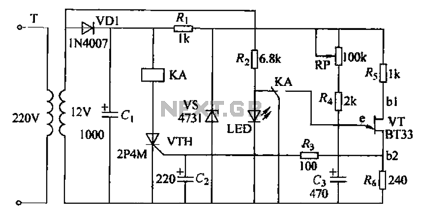
The circuit consists of a delay loop, discriminators, output circuits, power supply, and indicator lights, divided into five parts. The power regulation is achieved through a resistor (R), while the power regulator is constructed using a voltage source. In...
The transmitter features a VXO circuit that drives a keyed amplifier. This keyed amplifier powers an MRF 476 final amplifier, producing approximately 2 watts of output. Additionally, a solid-state T-R switch is incorporated for the receiver. The component values...
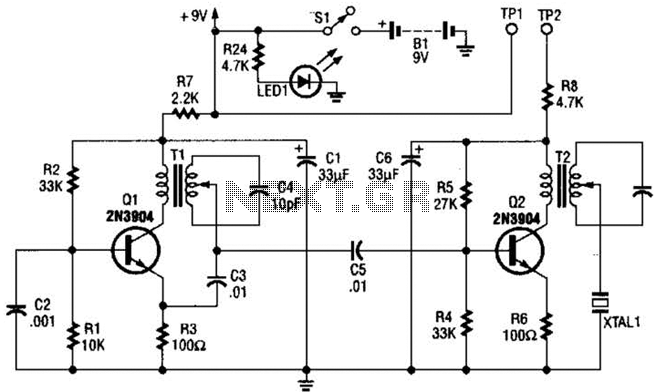
This design integrates power-on and low-battery indications, capable of operating with any battery voltage up to 15V. It features a very low current drain of 2mA or less and costs less than $3.50 with new components. When the battery...
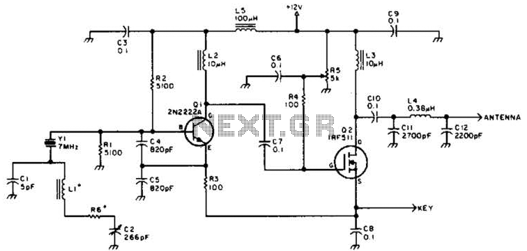
A DSB transmitter is significantly less expensive to construct compared to an SSB transmitter since it does not require filters or phasing networks. This circuit can generate an output of up to 1 watt on the 10-meter band. The...
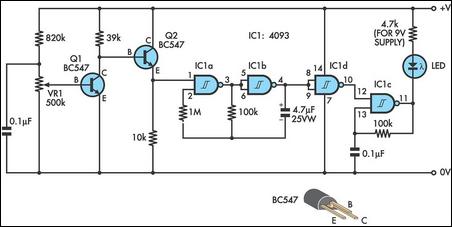
This is an enhanced infrared (IR) remote control extender circuit that exhibits high noise immunity, resistance to ambient and reflected light, and an extended operational range of approximately 7 meters between the remote control and the extender circuit. It...
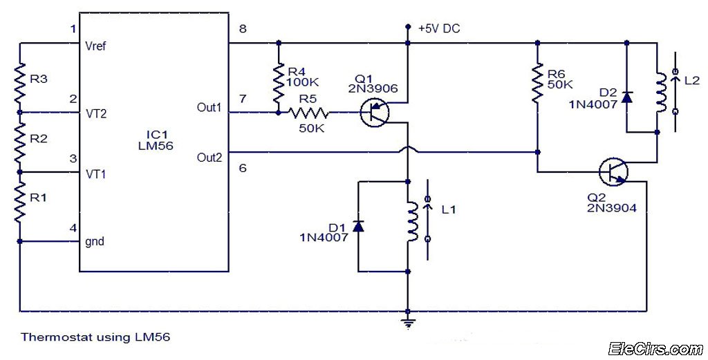
The LM56 Thermostat Project Circuit Diagram includes a schematic for the LM56 thermostat. The values of resistors R1, R2, and R3, which determine the required trip points VT1 and VT2, can be calculated using the following equations: VT1 =...