
ultrasonic measurement circuit

The electrostatic transducer circuit designed for ultrasonic measurement utilizes the LM1812 ultrasonic transceiver, which is a highly integrated device capable of both transmitting and receiving ultrasonic signals. The operation begins with the transducer (X1) generating a burst of ultrasonic oscillations. This burst travels through the medium until it encounters an object, at which point some of the sound energy is reflected back towards the transducer.
Upon receiving the echo, the LM1812 processes the signal. It is essential that the echo has sufficient amplitude to be detected; otherwise, the system will not register the return signal. The LM1812 is designed to produce a pulse that matches the width of the initial transmission burst, providing a direct correlation between the transmitted and received signals.
The timing of the echo is critical for distance measurement. If the echo returns quickly, it suggests that the reflecting object is close to the transducer. Conversely, a delayed echo indicates a greater distance. The circuit is designed to measure distances ranging from approximately 4 inches to 30 feet, making it suitable for various applications where precise distance measurement is required.
The transducer X1 is characterized by a capacitance of 500 pF. This capacitance is integral to the tuning process, as it resonates with the inductor L6 at the operational frequency of 50 to 60 kHz. The tuning of L1 is also a vital aspect of the circuit design. By adjusting L1 and observing the output on an oscilloscope connected to pin 1 of the LM1812, the user can achieve optimal echo sensitivity. This ensures that the circuit can effectively detect echoes over the intended measurement range.
In summary, the combination of the LM1812 transceiver and the electrostatic transducer X1 creates an effective ultrasonic measurement circuit capable of accurately determining distances based on the time-of-flight of ultrasonic waves. The careful selection of components and tuning procedures are crucial for achieving the desired performance and sensitivity in various measurement scenarios.This is a design circuit for an electrostatic transducer for ultrasonic measurement circuit. This circuit uses the LM1812 ultrasonic transceiver. Transducer x1 and LM1812 will transmit a burst of oscillations. Then the return echo is listened by using X1. The LM1812 detector will generate a pulse of the same width as the original burst when the X1 receive an echo of sufficient amplitude. If the return echo is early, it`s mean the object is near. This is the figure of the circuit; If the parts and values shown are used, this circuit has a range of about 4 inches to 30 feet. The X1 has a 500-pF capacitance that resonate with the L6 at 50 to 60kHz. The L1 is tuned to this frequency by watching for maximum echo sensitivity with a scope at pin 1. [Circuit diagram source: National Semiconductor Linear Application] 🔗 External reference
Related Circuits

This is a circuit design for a doorbell that produces a sound resembling that of a bird. The circuit is controlled by an NPN transistor. The operation begins when P1 is set to an experimental value, starting with approximately...
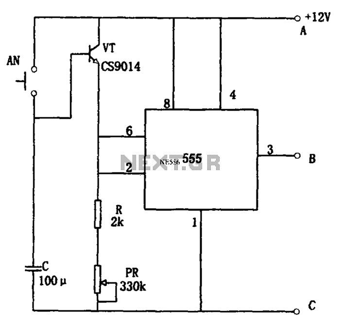
The circuit features a straightforward long timing mechanism. Activating switch AN initiates the timing process, while tone PR allows for timing adjustments. The timing range spans from 3 minutes to 220 minutes. With a capacitance value of 2200 µF,...
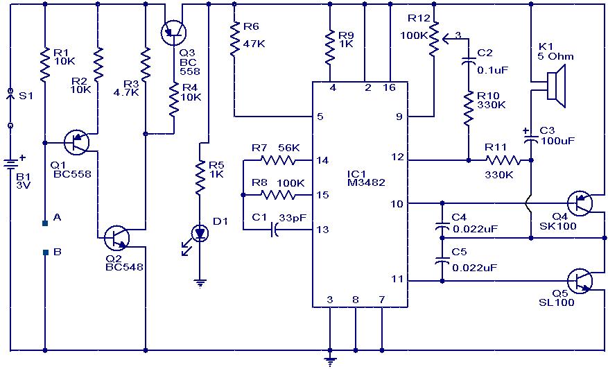
This circuit is a simple musical alarm that generates a tone when water or another conductive liquid touches the two sensor wires provided. It utilizes four transistors and a melody generator integrated circuit (IC) M3482. When water bridges the...
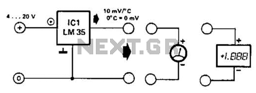
An effective temperature sensor circuit is designed to receive power from a 4-to-20 mA loop without impacting the loop current. The temperature sensor integrated circuit (IC) used is the AD590F, which operates with a supply voltage ranging from 4...
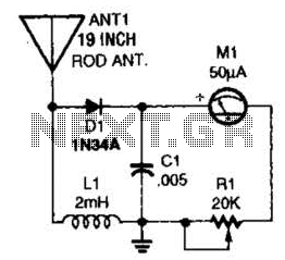
This basic field-strength meter offers an affordable solution for monitoring an amateur radio or CB transmitter, as well as an antenna system, to ensure maximum output. The field-strength meter is designed to measure the strength of radio frequency (RF) signals...
All electronic circuits were initially built on breadboards. Once the circuits were operational, they were soldered onto perfboards to create a more durable system. A power board was designed to stack two batteries in series, providing access to a...