
Simple Field Strength Meter Ii Circuit

The field-strength meter is designed to measure the strength of radio frequency (RF) signals emitted by transmitters or received by antennas. Its primary function is to provide users with a visual indication of signal strength, which can be invaluable for optimizing the performance of radio equipment.
The circuit typically consists of a few key components: an RF detector, a meter (often a galvanometer or digital display), and a calibration mechanism. The RF detector converts the incoming RF energy into a proportional DC voltage, which is then displayed on the meter. The calibration mechanism allows users to adjust the meter reading to correspond to specific signal strengths, ensuring accurate measurements.
To enhance usability, the circuit may include a variable resistor or potentiometer, allowing for fine-tuning of the sensitivity. Additionally, incorporating a simple antenna, such as a dipole or monopole, can improve the meter's performance by ensuring it is properly tuned to the frequencies of interest.
For construction, a compact PCB (Printed Circuit Board) can be utilized to house the components, ensuring a neat arrangement and minimizing interference. The power supply for the meter can be sourced from a standard battery or an external power supply, depending on the design requirements.
Overall, this field-strength meter serves as a practical tool for amateur radio enthusiasts, enabling them to effectively monitor and optimize their transmission systems. This simple field-strength meter provides a cheap way to monitor an amateur radio or CD transmitter (or even an antenna system) for maximum output.
Related Circuits
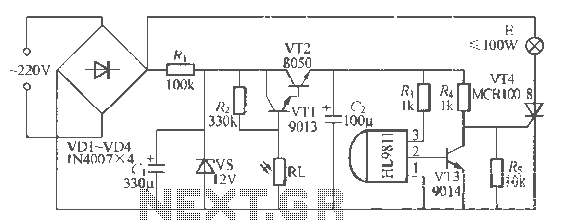
The H1.9811 single-channel flash control integrated circuit from Wuxi Love Core Microelectronics Co., Ltd. is designed for controlling flashing warning lights in road barricades. It features an integrated internal RC oscillator, frequency divider, output buffer amplifier, shaping circuit, and...
This UHF transmitter is designed for low power applications such as remote controls for garage doors, operating systems, and wireless alarms. This UHF FM transmitter is equipped with... This UHF transmitter operates within the Ultra High Frequency (UHF) band, which...
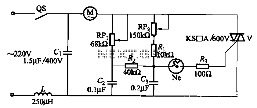
The 3P10 circuit, illustrated in the figure, utilizes a bidirectional thyristor for control. The adjustment potentiometer RPi allows for modification of the minimum motor speed, while the adjustment potentiometer RP2 enables continuous variation of the motor speed, reaching up...

Quasi square wave resonant converters, also referred to as quasi resonant (QR) converters, facilitate the design of flyback Switch Mode Power Supplies (SMPS) with diminished Electro Magnetic Interference (EMI) and enhanced efficiency. Due to their low noise generation, QR...
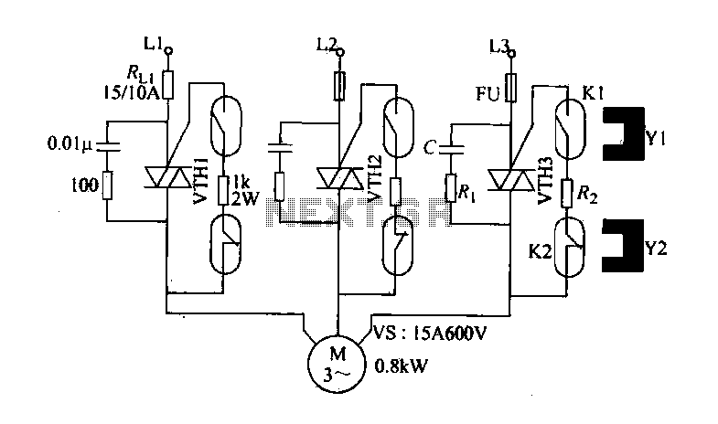
The circuit diagram illustrates a female textile machine power control circuit. VTH1-VTH3 represent TRIACs, while R and C form the absorption line. Rz serves as the triggering current limiting resistor. K1 is designated for starting the reed, and K2...
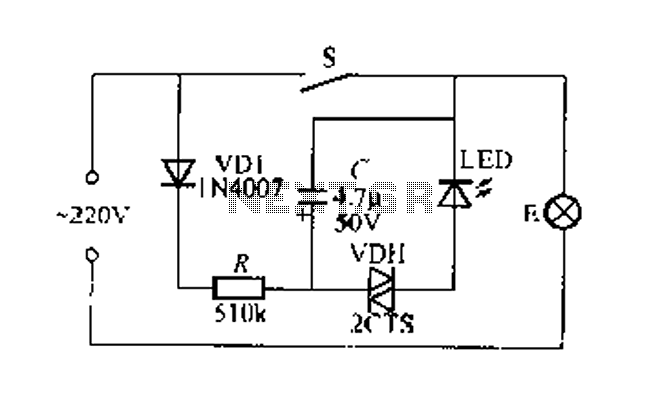
Figure 2 illustrates a circuit for a flashing light switch indicator. When switch S is closed, the normal light E illuminates, while the flashing light indicates a power loss when the system is not operational. When switch S is...