
Ultrasonic Mosquito Repeller Circuit Using CMOS IC

The ultrasonic mosquito repeller circuit is designed to emit sound waves that are inaudible to humans but can disrupt the behavior of mosquitoes and other insects. The core component, the CD4047 CMOS IC, is configured to function as a free-running oscillator. This oscillator generates a square wave signal at a frequency of 22 kHz, which is within the ultrasonic range.
The output from the CD4047 is fed into a complementary symmetry amplifier, which consists of four transistors arranged to provide the necessary gain for the signal. This configuration ensures that the output signal is strong enough to drive the piezo buzzer effectively. The complementary symmetry amplifier is advantageous as it enhances efficiency and reduces distortion in the amplified signal.
The piezo buzzer serves as the transducer that converts the amplified electrical signal into ultrasonic sound waves. The choice of a general-purpose piezo buzzer allows for flexibility in component selection while ensuring adequate performance for the application. The ultrasonic sound produced is intended to interfere with the sensory perception of mosquitoes, thereby repelling them from the area.
Powering the circuit with a 12V DC supply is a common choice, providing sufficient voltage for the operation of the CMOS IC and the amplifier. It is important to ensure that the IC is securely mounted on a holder to prevent mechanical stress that could affect its performance. Overall, the design of this circuit is straightforward and effective for individuals seeking a non-chemical method of pest control.This is the design circuit diagram of an ultrasonic mosquito repeller. The circuit is work with based on the theory that insects like mosquito can be repelled by using sound frequencies in the ultrasonic (above 20KHz) range. This is the figure of the circuit. This circuit is operated using CMOS IC CD4047. The circuit is nothing but a PLL IC CMOS 4 047 wired as an oscillator working at 22KHz. A complementary symmetry amplifier consisting of four transistor is used to amplify the sound. The piezo buzzer converts the output of amplifier to ultrasonic sound that can be heard by the insects. The circuit can be powered from 12V DC. The IC1 must be mounted on a holder. The buzzer can be any general purpose piezo buzzer. 🔗 External reference
Related Circuits

Using a Motorola MC34118 speakerphone IC, this adapter can be utilized with a standard telephone to enable speaker functionality. The device is powered from the phone line; however, it can also be powered through an external power supply if...
This circuit utilizes an MC3392 low-side protected switch in conjunction with an MC1455 timing circuit to create a dimmer control for automotive instrumentation panel lamps. The brightness of incandescent lamps is adjustable through Pulse Width Modulation (PWM) applied to...
The Reaction Capability Tester is utilized to assess and enhance an individual's quick-response abilities. It features various designs, with the depicted model comprising a CD4017 decimal counter and a light-emitting diode (LED). The construction of the Reaction Capability Tester...

This is a simple power resumption alarm circuit that can be installed within the switch box. It emits beeping sounds when power is restored following a power failure. The power resumption alarm circuit is designed to provide an audible alert...
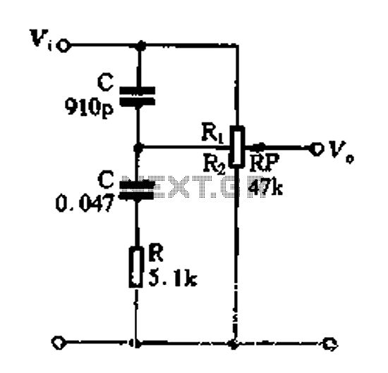
Figure 1-89 illustrates a loudness control circuit. A potentiometer is connected to ground, with 30% of the total resistance at the tap. When the slider arm is adjusted to the tap position, a midrange attenuation of 30 dB is...

This function generator, based on an LT1016 high-speed comparator, will generate from a single +5-V supply. The slow rate of the op-amps used determines the maximum usable frequency of this circuit. The function generator utilizes the LT1016 high-speed comparator to...