
Power Resumption Alarm circuit

The power resumption alarm circuit is designed to provide an audible alert upon the restoration of electrical power after an interruption. The circuit typically consists of a few essential components: a power supply, a microcontroller or a simple timer, a piezo buzzer, and various passive components such as resistors and capacitors.
Upon the restoration of power, the circuit is activated. A capacitor may be used to hold a charge temporarily, allowing the microcontroller or timer to initiate the beeping sequence. The microcontroller can be programmed to control the duration and frequency of the beeps, ensuring that the alarm is both effective and not overly intrusive.
The piezo buzzer serves as the output device, generating sound when triggered by the control circuit. The design may also incorporate a push-button switch that allows users to silence the alarm if desired. Additionally, a resistor-capacitor (RC) network could be implemented to create a delay before the alarm activates, preventing false alarms due to brief power fluctuations.
This circuit can be compactly housed within a switch box, making it convenient for residential or commercial applications. The installation process involves connecting the circuit to the existing power lines, ensuring proper insulation and safety measures are observed. The simplicity and effectiveness of this alarm circuit make it a valuable addition to any electrical system, providing peace of mind during power outages.Here is a simple power resumption alarm circuit that can be fixed inside the switch box itself. It gives beeps when the power resumes after a power failure.. 🔗 External reference
Related Circuits
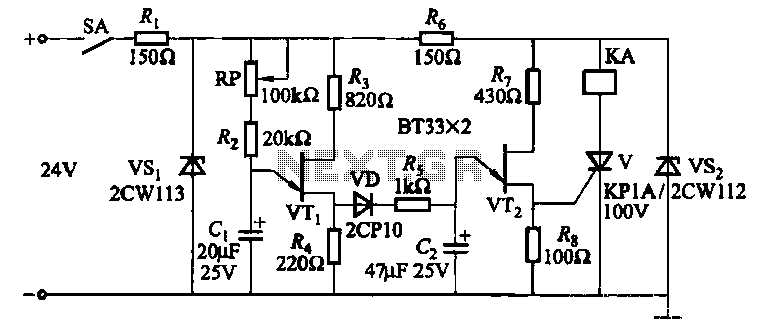
This circuit consists of three single-junction transistor time relay circuits utilizing a pulse charging mechanism, allowing for extended delay times of up to several minutes. The first stage delay circuit incorporates unijunction transistors (VTi) and other components, where capacitor...
The amplifier is based on the commonly used class-AB complementary power amplifier with compound pair output transistors. The system uses a TL074 quad opamp to drive the output transistors. As can be seen from figure 1, A2 is used to...

This device enables two computers to share a single USB printer or other USB devices such as an external flash drive, memory card reader, or scanner. A rotary switch is used to select the PC that will connect to...
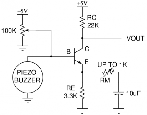
Piezo buzzers are widely used components. When disposing of an old smoke detector, it is advisable to extract the piezoelectric element for future use. Monitoring sound with a piezoelectric element can be challenging due to the low voltage it...
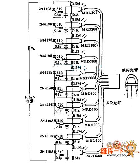
Light emitted by a Xenon flash tube is transmitted to the phototransistor MRD300 through an optical fiber. The sensitive current is amplified to trigger a series of thyristors simultaneously. Consequently, a high voltage of 6000V is applied to loader...
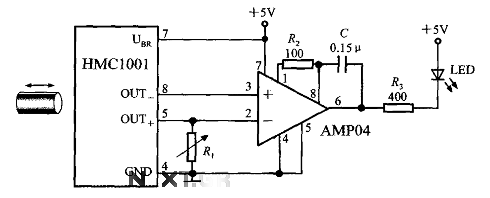
The circuit depicted in the figure includes the HMC1001 magnetic sensor, an operational amplifier (AMP04), and a light-emitting diode (LED), forming a proximity switch circuit. In this application, the operational amplifier functions as a comparator. When a magnet, approximately...