
ultrasonic transmitter 40khz

A second ultrasonic transmitting circuit employs transistors VT1 and VT2 to form a strong feedback resonant oscillator, with the oscillation frequency matching the resonant frequency of the ultrasonic transducer (T40-16). T40-16 acts as the feedback coupling element, and the output is derived from this transducer. The waveform at both ends of T40-16 resembles a square wave, with a voltage amplitude close to the power supply voltage. A switch (S) enables the circuit; when activated, it drives T40-16 to emit a series of 40kHz ultrasonic signals. The circuit operates at 9V with a current draw of approximately 25mA, capable of transmitting ultrasonic signals over distances greater than 8 meters without requiring adjustments.
The third 40kHz ultrasonic transmitter circuit utilizes positive feedback from transistors VT1 and VT2 to create a feedback oscillator, with the oscillation frequency dependent on the feedback element T40-16, maintaining a resonant frequency of 40kHz ± 2kHz. This configuration ensures frequency stability, with no need for adjustments. The T40-16 serves as the ultrasonic signal transducer, while an inductor (L1) and capacitor (C2) are used for resonance tuning at 40kHz. The circuit is designed to operate across a wide voltage range (3-12V) and can accommodate frequency variations. Fixed inductors with an inductance of 5.1mH are employed, and the machine draws approximately 25mA, capable of transmitting ultrasonic signals over distances greater than 8 meters.
The fourth 40kHz ultrasonic transmitter circuit comprises four complete non-oscillatory circuits and utilizes the CC4011 NAND gate to drive the ultrasonic transducer (T40-16) and control the receiver for ultrasound radiation. The circuit includes a controlled oscillator formed by gates YF1 and YF2, which starts oscillating when switch S is pressed. The oscillation frequency can be adjusted using RP to maintain 40kHz. Oscillations are managed by gates YF3 and YF4, where YF3's output high results in YF4's output low, and vice versa. The T40-16 is controlled to issue 40kHz signals. The YF1 to YF4 gates are high-speed CMOS circuits (74HC00), capable of driving current greater than 15mA with high efficiency. The circuit operates at 9V with an operating current exceeding 35mA, transmitting ultrasonic signals over distances greater than 10 meters.
The fifth 40kHz ultrasonic transmitting circuit features a time base circuit based on the LM555 timer and external components, forming a 40kHz multivibrator. The oscillation frequency can be altered by adjusting the resistance of RP. The output from pin 3 of the LM555 drives the ultrasonic transducer (T40-16) to emit ultrasonic signals. This circuit is straightforward and user-friendly, operating at 9V with a working current of 40-50mA, capable of transmitting ultrasonic signals over distances greater than 8 meters. The LM555 can be replaced with the NE555, yielding the same performance.40kHZ one ultrasonic transmitter circuit, the F1 ~ F3 three oscillators in the F3 is 40kHZ square wave output, frequency mainly by C1, R1 and RP decided to adjust the adjustable resistance with a frequency of RP. F3 transducer excitation output T40-16 at one end and the inverter F4, F4 transducer excitation output T40-16 the other end, therefore,
join F4 doubling the excitation voltage. Capacitors C3, C2 and F4 F3 balance the output of the waveform is stable. Inverter circuit, F1 ~ F4 with the CC4069 in four of six inverter inverter, and the remaining two do not (input should be grounded. ) Power Supply 9V laminated battery. F3 output frequency measurement should be 40kHZ ± 2kHZ, or should be adjusted RP. Transmitting ultrasonic signals greater than 8m. 40kHZ second ultrasonic transmitting circuit, the circuit transistors VT1, VT2 form strong feedback resonator oscillator, the oscillation frequency equal to the ultrasonic transducer T40-16 resonant frequency.
T40-16 is the feedback coupling element, the circuit is the output for the transducer. T40-16 is similar at both ends of the square wave oscillation waveform, voltage amplitude close to the power supply voltage. S is the power switch, click S, T40-16 can drive a string of 40kHZ emitted ultrasonic signals. Circuit voltage of 9V, the operating current of about 25mA. Transmitting ultrasonic signals greater than 8m. Circuit can work without debugging. 40kHZ ultrasonic transmitter circuit, produced by the VT1, VT2 positive feedback form feedback oscillator.
Circuit oscillation frequency depends on the feedback element of the T40-16, the resonant frequency of 40kHZ ± 2kHZ. Frequency stability, no need to make any adjustment by the T40-16 as a transducer of the ultrasonic signals emitted 40kHZ.
Inductor L1 and capacitor C2 for resonance tuning role played in the 40kHZ. Voltage of the circuit to adapt to a wide (3 ~ 12V), and the frequency change. Using fixed inductors, inductance 5. 1mH. Machine operating current of about 25mA. Transmitting ultrasonic signals greater than 8m. 40kHZ four ultrasonic transmitter circuit, which consists of four complete and non-oscillation, and gate drive functions CC4011 by ultrasonic transducer T40-16 to control the receiver, the ultrasound radiation. Which formed the door YF1 controlled oscillator with the door YF2, when S is pressed, the oscillator start-up, adjust the RP change the oscillation frequency, should be 40kHZ.
Oscillations are controlled by YF4, YF3 drive differential phase composition of the work, when YF3 output goes high, YF4 certain output low; YF3 output low, YF4 output high. The T40-16 level control issue 40kHZ ultrasonic transducer. Circuit YF1 ~ YF4 four high-speed CMOS circuit 74HC00 NAND gate circuit, the output drive current is characterized by large (greater than 15mA), high efficiency.
Circuit voltage of 9V, operating current greater than 35mA, transmitting ultrasonic signal is greater than 10m. 40kHZ five ultrasonic transmitting circuit, time base circuit by the LM555 and the external components, the 40kHZ multivibrator circuit, adjust the resistance of resistor RP can change the oscillation frequency.
3 feet from the LM555 output drives ultrasonic transducer T40 -16, so that emit ultrasonic signals. Circuit is simple and easy system. Circuit voltage of 9V, working current 40 ~ 50mA. Transmitting ultrasonic signals greater than 8m. LM555 NE555 direct replacement is available, the effect is the same. 🔗 External reference
Related Circuits
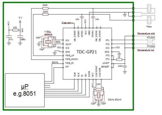
Enhancements include an analog front end, pin-to-pin compatibility for existing designs, an analog stabilized comparator, and simplified external circuit design. There is improved time and temperature measurement with reduced current consumption. The TDC-GP21 is ideally suited for designing compact...
This compact transmitter employs a Hartley-type oscillator. Typically, the capacitor in the tank circuit would connect to the base of the transistor; however, at VHF frequencies, the base-emitter capacitance of the transistor behaves like a short circuit, effectively maintaining...
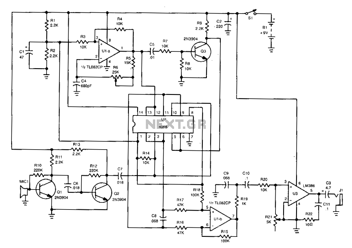
The piezo speaker, MIC1, detects the incoming ultrasonic signal and transmits it to the base of Q1. A two-transistor booster amplifier composed of Q1 and Q2 amplifies the signal to a level adequate for driving one input of this...
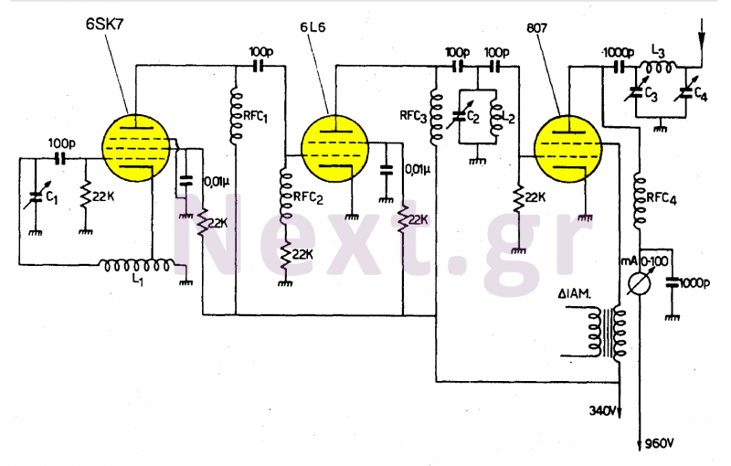
This transmitter operates in the shortwave range from 6 MHz to 22 MHz. Coil L1 serves as the shortwave oscillating coil for the 6SA7 vacuum tube and is commercially available. Capacitor C1 is a variable capacitor with a capacitance...
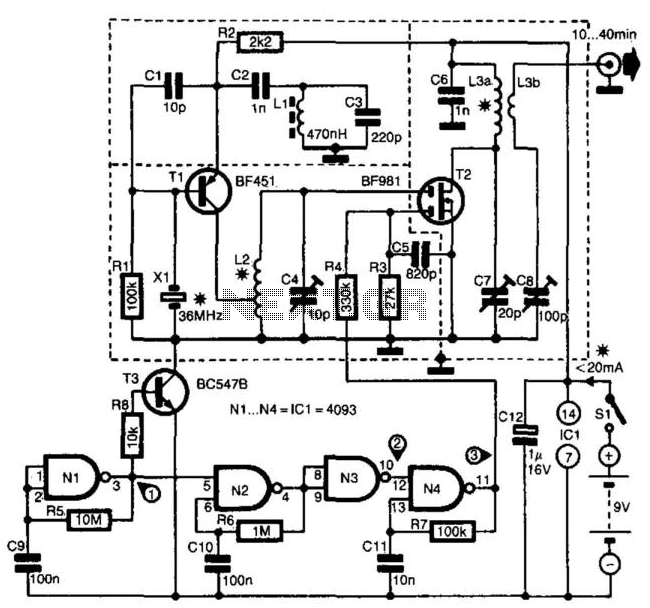
The transmitter is specifically designed for radio amateurs to function as a radio beacon, delivering a high-quality signal devoid of unwanted harmonics. Transistor T1, in conjunction with crystal X1, serves as a 36-MHz oscillator. Filter L1/C3 prevents the circuit...
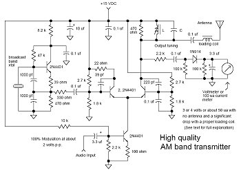
In many discussions of LPAM transmitter design, references to "the Wenzel circuit" or "the Wenzel transmitter" are common. These terms refer to a clever transmitter design that became popular in the mid-1990s and early 2000s for those interested in...