
Ultrasonic transmitter circuit

The ultrasonic transmitter circuit T-40-16 is designed to generate high-frequency ultrasonic waves for various applications such as remote sensing, object detection, or communication systems. The circuit architecture includes two key transistors, VT1 and VT2, which are configured to form a positive feedback oscillator. This configuration is crucial for ensuring that the oscillation frequency remains stable at 40 kHz, which is the operational frequency of the T-40-16 transmitter.
The circuit operates with a supply voltage of -9V, which is typical for low-power ultrasonic applications. The current consumption of 25mA indicates that the circuit is energy-efficient, making it suitable for battery-operated devices. The operational range of approximately 8 meters allows for effective transmission and reception of ultrasonic signals, making it ideal for applications where compactness and efficiency are essential.
When the switch S is activated, the circuit initiates the oscillation process, producing a series of ultrasonic pulses. These pulses can be received by compatible ultrasonic receivers, enabling communication or detection capabilities. The square wave output generated by the circuit is characterized by its voltage amplitude, which closely matches the power supply voltage, ensuring effective signal transmission.
The alternative circuit using the MA40EIS sensor operates similarly to the T-40-16, demonstrating the versatility of the design. The inductor L, connected to the collector of VT2, serves a dual purpose: it acts as a load resistance and enhances the excitation voltage. This design feature allows for increased power transmission, which is beneficial for applications requiring longer-range ultrasonic communication or enhanced sensitivity in detecting reflected signals.
Overall, the T-40-16 ultrasonic transmitter circuit represents a well-engineered solution for generating ultrasonic waves, with its robust feedback mechanism and efficient power handling capabilities contributing to its effectiveness in various electronic applications.Given by the ultrasonic transmitter circuit T-40-16 and other discrete components. T-40-16 as a feedback sensor element and the electrical circuit of the transistors VTI, VT2 form a strong positive feedback oscillator frequency, the electric signal into an ultrasonic oscillation signal, the oscillation frequency is equal to the center frequency of the ultrasonic transmitter of the T-40-16 40kHz. The circuit work oak, T-40-16 is similar oscillation waveform generated across the square wave pulse voltage amplitude close to the power voltage faction.
When you press the switch S, can emit a series of 40kHz ultrasonic signal transmitter to the receiver of ,,. The circuit operating voltage geese -9V, operating current 25mA, remote control distance of up to about 8m.
As shown 18-60h given ultrasonic transmitter circuit MA4 0EIS / EIR and other discrete components. Works same as in Figure 18-60a, different sensor is MA40EIS. Its structure, properties and T-4 0-16 similar. In addition, the VT2 collector inductor L as the load resistance, in order to facilitate increased excitation voltage, so Nusheng wave transmitter capable of transmitting more power, but also to improve its resonance characteristics of the role
Related Circuits
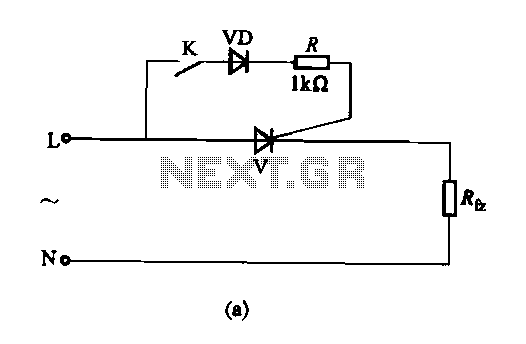
The thyristor AC switch circuit is not triggered, due to its simplicity, cost-effectiveness, and non-contact operation, making it widely utilized. The circuit is illustrated in Figure 16-43. It consists of single-phase thyristor switching circuits. Figure 16-43 (a) depicts a...
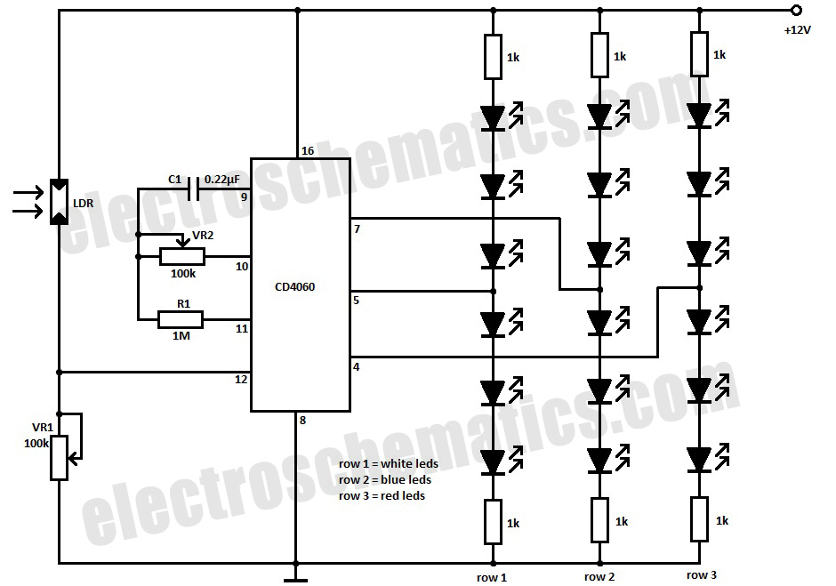
This simple Christmas LED lights decoration circuit allows for the creation of an 18 LED flasher to adorn a Christmas tree. The circuit incorporates white, blue, and red LEDs that flash in a festive pattern. The circuit is designed to...
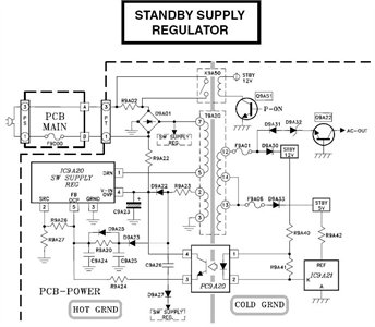
The schematic is in PDF format and cannot be sent through this site. It is recommended to check a specific website that contains various schematics, including older posts that might have the schematic needed. A WS-55807 model is experiencing...
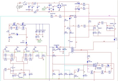
A Power Factor Correction (PFC) board has been obtained from an old Sun Microsystems Spark450 power supply (part number 300-1359-xx). This board contains all necessary components for a 650-watt inverter. However, the complete PFC circuit is not fully detailed...
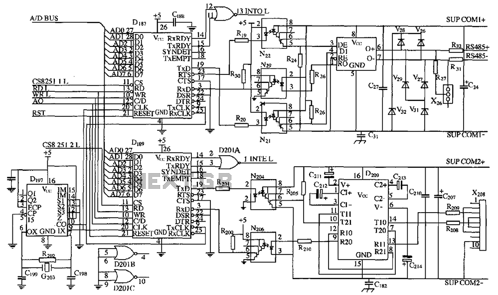
As shown in the figure, D187 is a universal asynchronous receiver-transmitter (UART). Its RX/TX signals are received through optocouplers N21, N22, and N29, facilitating RS-485 communication. The interface receiver/transmitter D28 and microprocessor D211 are completely optically isolated. D197 serves...
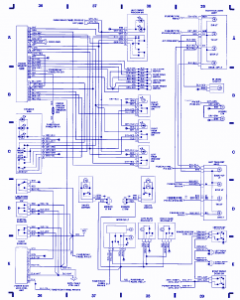
Emergency lights, fuse/relay panel, fresh air blower switch, engine control module, ignition coil, console switch, power windows, ABS control unit, ABS hydraulic unit, instrument cluster, taillight, headlight switch, automatic solenoid, ignition switch. The described circuit encompasses multiple essential components for...