
Purpose of SCRs in Power Factor Circuit

The Power Factor Correction (PFC) board in question is designed to enhance the efficiency of an inverter system by minimizing the phase difference between voltage and current. In typical PFC circuits, components such as inductors, capacitors, diodes, and transistors are utilized to regulate the input power and improve the overall power factor. The presence of SCRs in this specific design raises unique operational questions.
SCRs, or silicon-controlled rectifiers, are semiconductor devices that act as switches. They can control large amounts of power and are often used in applications requiring precise timing and control, such as phase control in AC circuits. In this context, the SCRs may serve a dual purpose: to rectify AC signals and to control the timing of current flow into the inductor, which is critical for maintaining desired voltage levels in the inverter.
The proposed configuration suggests that when the voltage level sensed by transistors Q3 and Q5 drops below a certain threshold, the SCRs are triggered to conduct. This conduction allows a portion of the AC current to flow into the inductor, thus maintaining the necessary energy levels for the inverter operation. The inductor, in turn, stores energy during this conduction phase and releases it when required, smoothing out the output voltage and improving the power factor.
To fully understand the operation of this circuit, it may be beneficial to analyze the triggering mechanism for the SCRs in conjunction with the feedback from Q3 and Q5. Investigating the timing and control signals that dictate when the SCRs are activated will provide insights into their role within the PFC circuit. Additionally, reviewing the overall circuit topology and component interactions will aid in clarifying the specific application of the SCRs in this design.I have a Power Factor Correction board that was taken from an old Sun Microsystem Spark450 power supply p/n 300-1359-xx. It has everything I need for a 650 watt inverter. The entire PFC circuit is not detailed in this image. The only part of the circuit I don`t understand is the purpose of the SCRs. I searched unsuccessfully for a circuit where th e cathodes of SCRs are tied together. I did find some very usesful SCR information from ON Semiconductor but nothing that matched. I have seen many PFC and Boost circuits, but none with SCR`s. My guess is that the SCRs inject a part of the half wave AC current into the inductor when the voltage level is sense by Q3/Q5 is low. Your help on this would be greatly appriciated. 🔗 External reference
Related Circuits
With this circuit we can create a altered sound of siren. The oscillator IC1a-b is constituted by two gates NAND, oscillating in very low frequency. This oscillation drive the IC2, that is a electronic switch, which opens and closes...
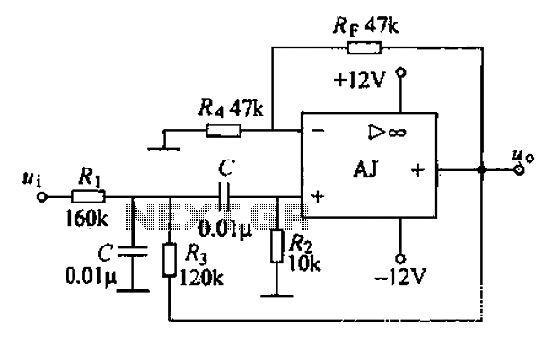
This circuit was submitted by Graham Maynard from Newtownabbey, Northern Ireland. It has an exceptionally fast high-frequency response, as demonstrated by applying a 100kHz square wave to the input. All graphs were produced using Tina Pro. The circuit in question...
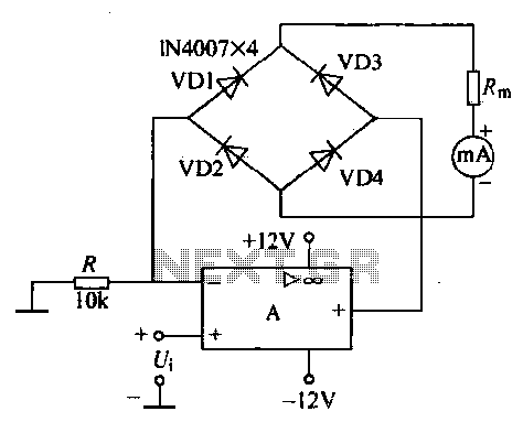
An operational amplifier, a diode bridge rectifier, and DC mA AC voltmeter tables are illustrated in the figure. The operational amplifier used is the LM324. The measured AC voltage is applied to the inverting terminal of the operational amplifier,...
A band-pass filter permits only signals within a specified frequency range to pass through, while attenuating or suppressing those outside this range. This is characterized by a lower frequency limit and an upper frequency limit. A typical implementation is...
This circuit measures the distance covered during a walk. The hardware is located in a small box that can be slipped into a pants pocket. The display is designed such that the leftmost display, D2 (the most significant digit),...
One of the simplest methods of metal detection is through a beat frequency oscillator. The circuit consists of two balanced oscillators: one provides a reference signal, while the other acts as the detector element. The frequency of the reference...