
Ultraviolet light source UV-80 for PCB exposure

The described automatic ultraviolet light source exposure box is a sophisticated device designed for efficient PCB manufacturing. It employs a streamlined control system that enhances usability and functionality. The integration of manual and automatic modes allows users to tailor the exposure process to their specific requirements.
The use of UV light for photoresist exposure enables the production of high-resolution PCBs with fine details, which is critical in modern electronics where miniaturization is prevalent. The capability to achieve track widths as narrow as 0.2 mm significantly expands design possibilities, making it suitable for high-density applications.
The timing controls provided by the MIN and SEC buttons facilitate precise exposure settings, essential for achieving optimal development of the photoresist layer. The inclusion of an LCD display for real-time feedback on exposure time enhances user interaction with the device, allowing for better monitoring and adjustments during the manufacturing process.
The design of the exposure box also considers safety and operational efficiency. The separate control of upper and lower lamps ensures that the exposure can be optimized for different board configurations, whether single or double-sided. The relays used to power the lamps provide a reliable means of managing the high voltage required for UV lamp operation, while the microcontroller's power control ensures stable operation of the entire system.
Overall, this automatic ultraviolet light source exposure box represents a significant advancement in PCB manufacturing technology, combining precision, speed, and user-friendly features to meet the demands of modern electronic design and production.One of more advanced PCB manufacturing methods is exposing laminate copper boards covered by photo resistive layer through mask. Using UV light in manufacturing PCBa‚¬ s has many benefits according to other methods: you can get thin tracks like 0.
2mm. You couldna‚¬ t do this by using other home techniques like laser printers or hand artwork; oth er advantage is that this method gives clean image a‚¬ smooth edges of PCB tracks. Little bit effort and you can compare results to commercial products. And pf course third benefit is speed and multiple replications of your boards by using the same mask. In this article is described the manufacturing of an automatic ultraviolet light source exposure box.
POWER switch is used to turn on/off power of the UV box. Green LED indicates the ON. MANUAL/AUTOMATIC switch is used to power l the UV lamps manually or automatically. Switches UPSIDE and UNDERSIDE are used to enable upper and lower lamps separately a‚¬ in case you are using single or double sided boards. When automatic mode is selected, then by pressing buttons MIN UP, MIN DOWN, SEC UP, SEC DOWN exposure time is selected.
START starts timer counter and powers the lamps through relays. STOP/CLEAR is not implemented yet. LCD displays the Time of exposure, and after start is pressed it shows remaining time of UV exposure. Control circuit is very simple. Buttons are connected directly to I/O pins through internal Pull-Up resistors. When button is pressed a‚¬ the a‚¬ 0a‚¬ level in port input is generated, which triggers an action. UV lamps are connected in series of 2 and then ballasts are connected. Starter is connected to lamps in parallel. Upper and lower covers of box can be controlled separately by using switch. In this circuit you can also see power control for microcontroller and relays. 🔗 External reference
Related Circuits
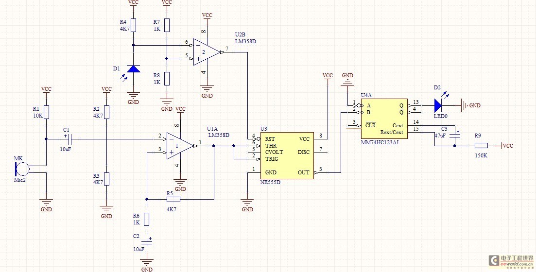
The function of this circuit is to detect a sudden shadow falling on the light sensor and to activate a buzzer when this occurs. The light sensor is designed to monitor ambient light levels. The circuit utilizes a light-dependent resistor...
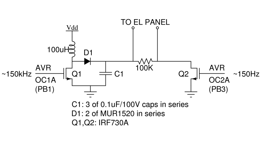
There are two primary types of backlights for LCDs: LEDs, which stands for light-emitting diodes, and EL, which stands for electroluminescent. EL backlights are generally more efficient and provide more uniform lighting compared to LED backlights, but they require...
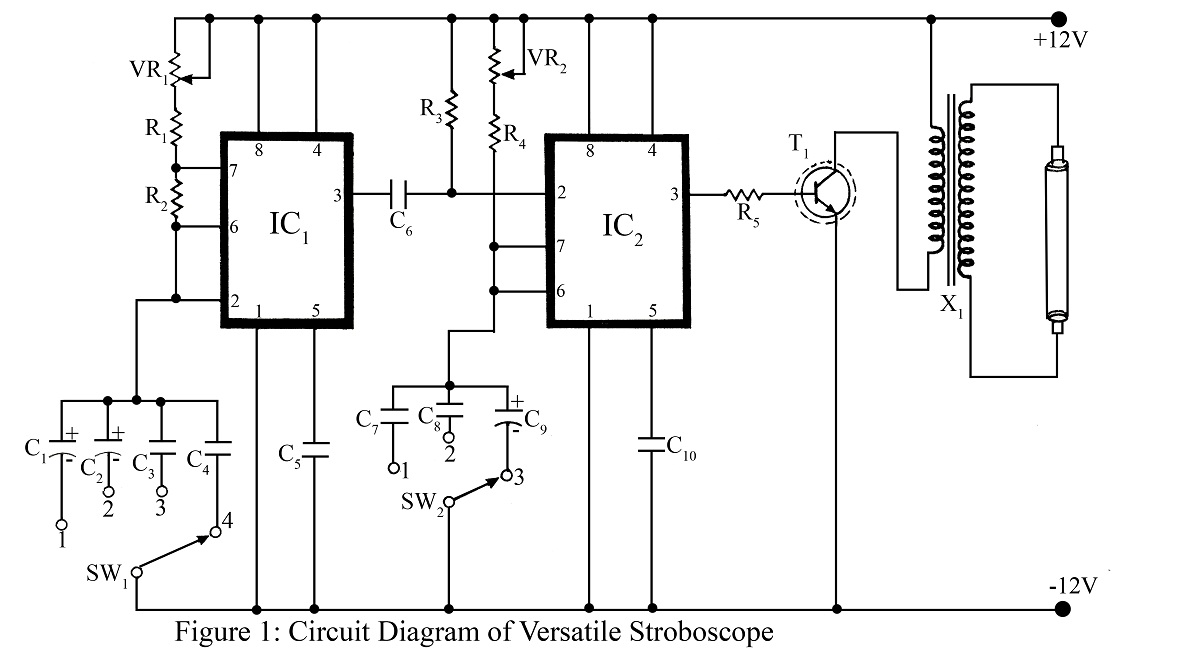
A stroboscope is an instrument used to observe rapidly moving objects with periodic motion as if they are stationary. The strobe light flashes at a frequency that synchronizes with the rotation of a wheel or moving object, creating the...
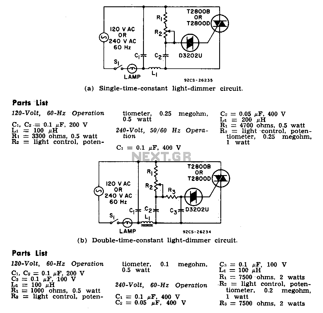
The two lamp-dimmer circuits differ in that one employs a single-time-constant trigger network, while the other uses a double-time-constant trigger circuit. This second configuration reduces hysteresis effects and extends the effective range of the light-control potentiometer. Hysteresis refers to...
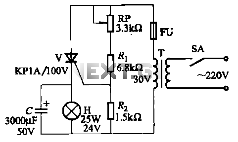
The circuit employs thyristor control. The flash frequency is determined by resistors Ri, RP, Rz, and capacitor C. By adjusting the electrical locator RP, the flash frequency can be varied from 0.5 Hz to several Hz. The described circuit utilizes...
The optically-controlled circuit plays a crucial role in urban street lighting and corridor illumination. By utilizing this circuit, lighting lamps can be automatically turned on and off based on ambient light levels, thereby reducing the need for manual control,...