
Light dimmers

The described lamp-dimmer circuits utilize distinct trigger networks to manage the operation of the lamp effectively. In the first circuit, the single-time-constant trigger network provides a straightforward approach to dimming, relying on a single capacitor to determine the timing of the gate pulse. This simplicity may lead to increased hysteresis, where the lamp's on and off states do not correspond to the same potentiometer settings, potentially causing user frustration.
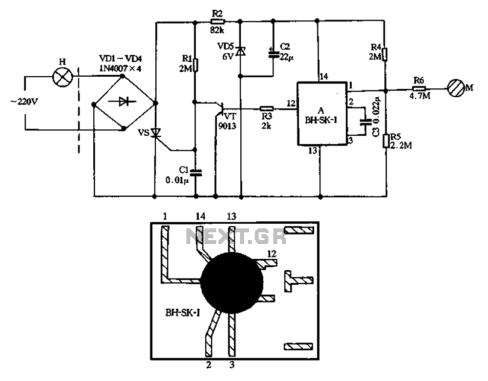
Conversely, the second circuit employs a double-time-constant trigger mechanism, which incorporates two capacitors, C2 and C3. This configuration is designed to mitigate hysteresis by allowing capacitor C2 to charge to a higher voltage than C3. The longer discharge time constant of C2 ensures that it can replenish the charge in C3 after the gate current pulse has been generated. This replenishment helps to stabilize the operation of the circuit, providing a more consistent dimming experience.
In this circuit, the operation begins with the gate triggering process, where C3 discharges to create a pulse that activates the gate. The characteristics of C3's discharge are critical to the timing of the pulse, dictating the moment the lamp turns on. Simultaneously, C2's role becomes significant as its longer time constant allows it to maintain a higher charge level, which in turn reduces the potential for hysteresis. As a result, the light-control potentiometer offers a wider range of effective control, enabling users to adjust the brightness of the lamp with greater precision and reliability.
Overall, the design of the double-time-constant trigger circuit represents an advancement in lamp-dimming technology, enhancing user experience by minimizing hysteresis and providing a more responsive control mechanism.The two lamp-dimmer circuits differ in that (a) employs a single-time-constant trigger network and (b) uses a double-time-constant trigger circuit that reduces hysteresis effects and thereby extends the effective range of the light-control potentiometer. (Hysteresisre-fers to a difference in the control potentiometer setting at which the lamp turns on and the setting at which the light is extinguished) The additional capacitor C2 in (b) reduces hysteresis by charging to a higher voltage than capacitor C3
During gate triggering, C3 discharges to form the gate current pulse. Capacitor C2, however, has a longer discharge time constant and this capacitor restores some of the charge removed from C3 by the gate current pulse.
Related Circuits
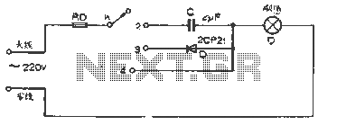
The figure illustrates a basic dimming lights circuit. The light intensity is controlled by a multi-speed control switch, designated as K. When switch K is set to position "1," the lights are turned off. In position "2," the light...
The BH-SK-I is a touch light switch circuit that integrates a single bond voice integrated circuit. The circuit is divided into two sections: the left section represents the general lighting lines, while the right section illustrates the touch switch....
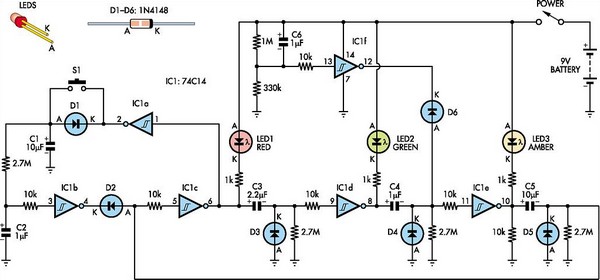
This toy traffic signal utilizes a single, cost-effective hex Schmitt-trigger inverter IC (IC1a-IC1f) to directly control three colored LEDs (red, green, and amber). Upon activation, the circuit illuminates the red signal for 30 seconds, followed by the green signal...

Using the SLB0586A integrated circuit from Siemens, it is possible to construct a straightforward touch light dimmer circuit that enables the user to adjust the intensity of a lamp. This circuit also incorporates a TIC206D component. The SLB0586A is designed...
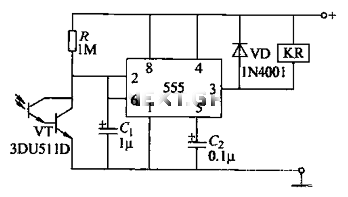
The circuit utilizes a Darlington-type phototransistor as the sensing element, which enhances sensitivity to low light levels, making it suitable for detecting reflected light signals. When the Darlington phototransistor is exposed to light, its resistance decreases, causing the voltage...
External circuit converts bass beat of music into pulses. The motor is controlled by them. If there's bass beat recognized then the motor rotates one direction (in full stepping) for a predefined time then stops. If the second beat...