
UM3561 high temperature detector circuit diagram

The heat detector alarm circuit operates on a principle of temperature sensing and sound generation, making it suitable for fire detection applications. The use of the UM3561 sound generator is central to producing the alarm sound, which mimics that of a fire engine, thus ensuring that it captures attention effectively.
The circuit's design incorporates a pair of transistors, T1 and T2, which work in tandem to detect changes in temperature. The T1 transistor acts as the primary sensor; when heat is detected, it transitions from a non-conductive to a conductive state, reducing the resistance between its emitter and collector. This change allows current to flow through T2, which is configured to respond to the output of T1.
The RL1 relay serves as an interface between the low-power transistor circuit and the high-power siren. When T2 is activated, it closes the relay contacts, allowing the siren to draw the necessary current from the power supply to operate effectively. The choice of a 6-volt DC supply ensures that both the relay and the siren receive adequate power for reliable operation.
For the UM3561 IC, the integration of a 3-volt zener diode is essential for stabilizing the voltage supplied to the sound generator. This configuration ensures that the sound output remains consistent, regardless of fluctuations in the power supply. The zener diode acts as a voltage regulator, thus protecting the UM3561 from over-voltage conditions that could damage the integrated circuit.
Overall, this heat detector alarm circuit is a practical solution for fire safety, combining simple electronic components with effective detection and alarm functionalities. Its design is straightforward, allowing for easy assembly and implementation in various settings, from residential to commercial environments.This heat detector alarm electronic project is designed using the UM3561 sound generator circuit and some other common electronic parts. This heat detector circuit project uses a complementary pair comprising npn and pnp transistor to detect heat.
When the temperature close to the T1 transistor is hot, the resistance to the emitter collector goes low and it starts conducting. In same time T2 transistor conducts, because its base is connected to the collector of T1 transistor and the RL1 relay energized and switches on the siren which produce a fire engine alarm sound. This electronic project must be powered from a 6 volts DC, but the UM3561 IC is powered using a 3 volt zener diode, because the alarm sound require a 3 volts dc power supply.
🔗 External reference
Related Circuits

This device is a simple timer that keeps the headlights of a vehicle on for approximately 1 minute and 30 seconds, allowing access to dark areas without the need to manually switch off the lights. Activating switch P1 initiates...

This is a compact collection of amplifiers configured in a bridge connection. The output power is low, making them suitable for general applications. They can be utilized with small active loudspeakers, car stereos, and similar devices. The only limitation...
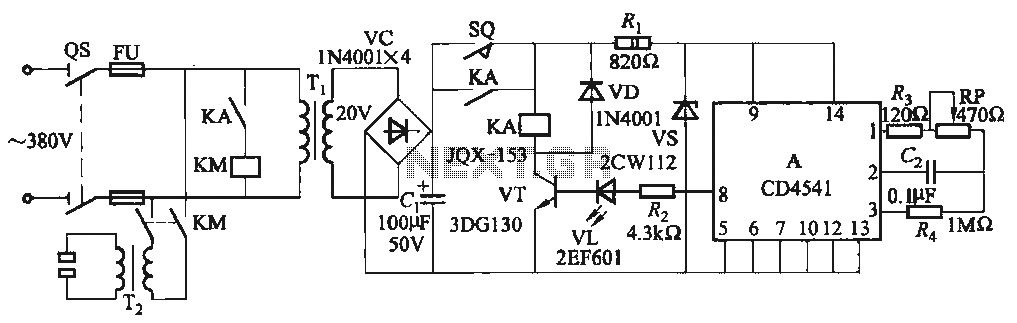
One Foot Spot Welder circuit. The circuit utilizes the IC CD4541 to provide precise delay characteristics, enabling the electrical time constant necessary for effective welding. This ensures consistent welding quality across identical weldments. For varying weldments, the electrical locator...
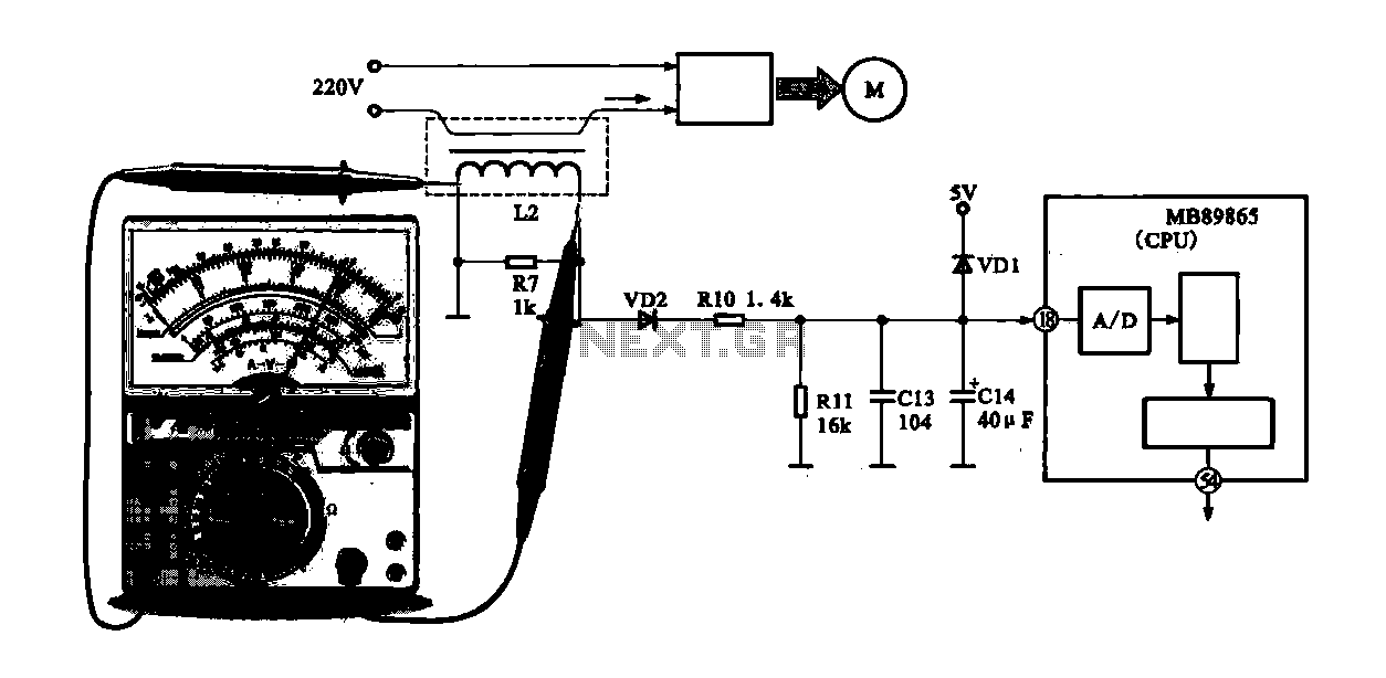
A current-voltage conversion circuit is commonly utilized in current detection applications. An example is the current detection circuit for a ring inverter air conditioner, which primarily serves to monitor the supply current of the compressor motor. Excessive current can...
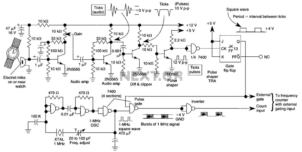
This circuit adapts a frequency counter to measure intervals. It was originally utilized as a shutter speed checker for photographic applications. The watch ticks are clipped, shaped, and formed into a square wave. This square wave is employed to...
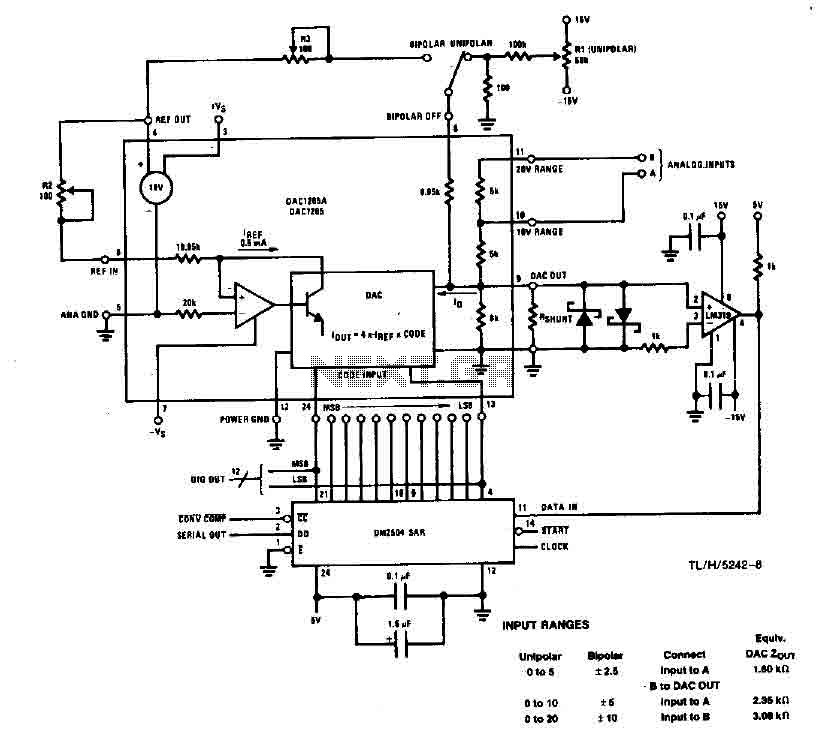
This system performs a complete conversion of 12 bits in both unipolar and bipolar modes. The converter is accurate to ±12-bit LSB with a typical gain temperature coefficient of 10 ppm/°C. In unipolar mode, the system operates within a...