
UM91214B IC For Radio Remote Control

The Radio Remote Control Circuit utilizes the UM91214B integrated circuit, which is specifically designed for DTMF applications. In this configuration, the circuit is capable of receiving DTMF signals transmitted from a remote control unit, allowing for the control of various devices wirelessly.
The circuit typically consists of a transmitter and a receiver. The transmitter includes a keypad that generates DTMF tones when buttons are pressed. These tones are then modulated onto a radio frequency (RF) carrier signal, which is transmitted over the air. The receiver, which incorporates the UM91214B IC, demodulates the incoming RF signal and decodes the DTMF tones back into their original binary format.
Key components of the circuit include an RF transmitter module, an RF receiver module, the UM91214B IC, a microcontroller for processing the decoded signals, and output drivers that control the devices being operated. Power supply considerations are also essential; typical configurations utilize a regulated power source to ensure stable operation of the circuit.
The design allows for multiple control commands to be sent simultaneously, making it suitable for applications such as remote lighting control, garage door openers, and other home automation tasks. The circuit’s range, reliability, and ease of use make it an effective solution for wireless control applications.The following circuit shows a Radio Remote Control Circuit Diagram. This circuit based on the UM91214B IC. Features: use of DTMF (dual-tone .. 🔗 External reference
Related Circuits
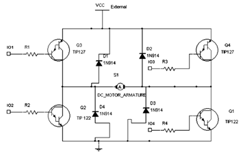
The diagram below illustrates an H-Bridge circuit featuring four inputs and an external power supply. The control application must enable the motor to operate in both forward and reverse directions. The H-Bridge is a crucial component in motor control applications,...
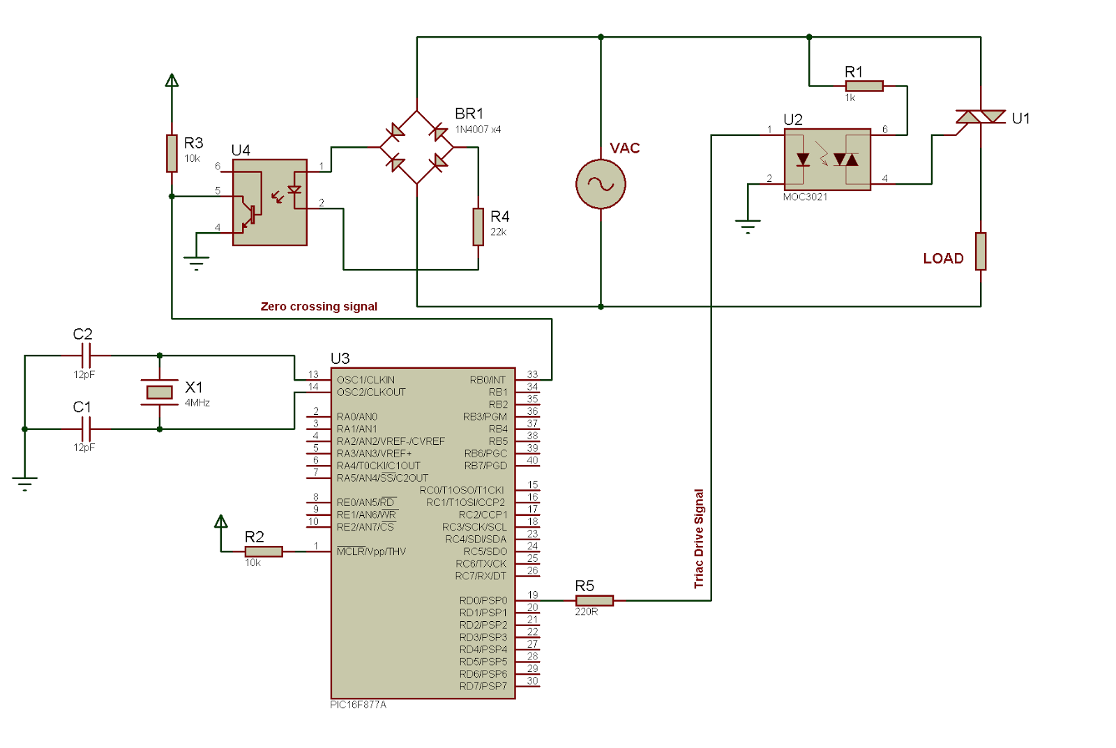
The image above clearly demonstrates phase angle control, where the output voltage is regulated by the gate drive signal applied to a thyristor. Phase angle control is a technique of pulse width modulation (PWM) used with alternating current (AC)...
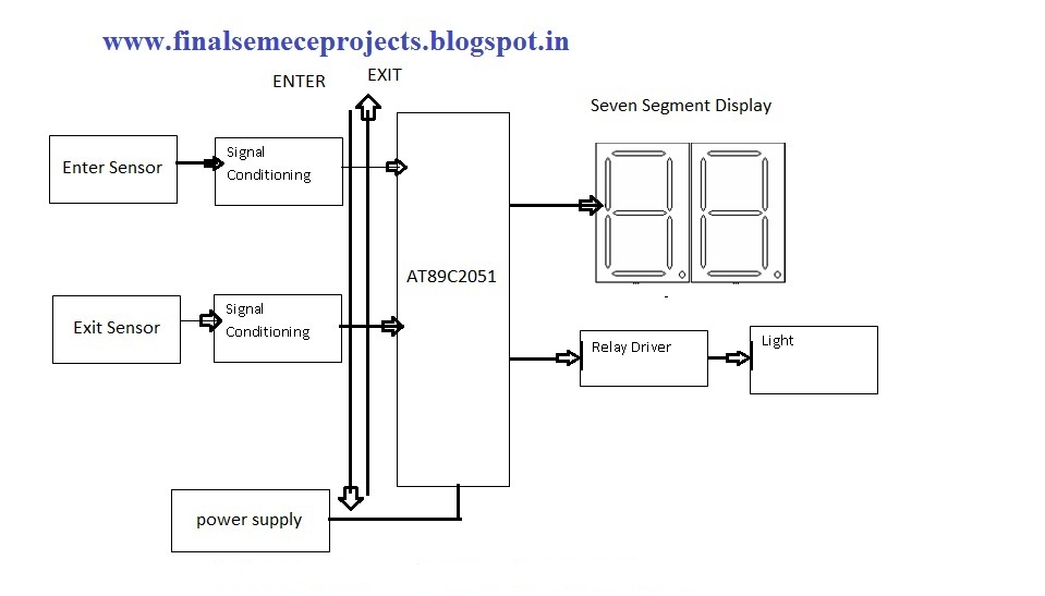
This project involves an automatic room light controller with a bidirectional visitor counter using a microcontroller. It is designed to manage room lighting and accurately count the number of individuals present. When a person enters the room, the counter...

The schematic for controlling the motors is divided into three main sections, each serving a distinct function. The primary components featured in the schematic include the PIC 18F252 microcontroller, the SN754410 motor driver, and 2N2222 transistors. At the top...
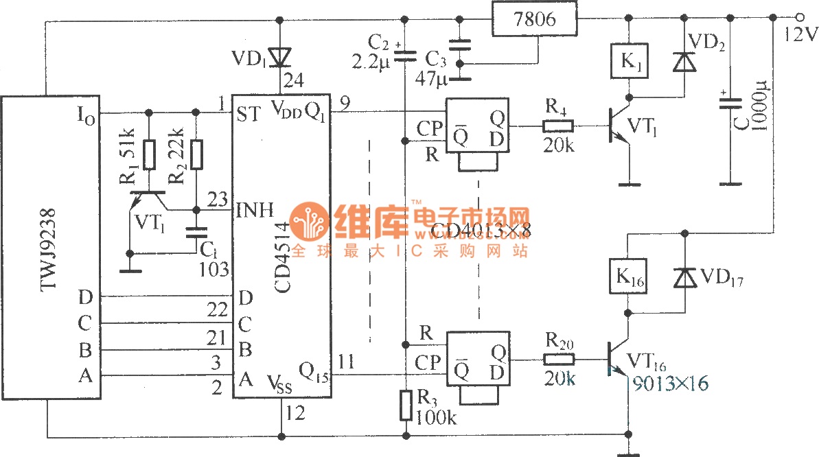
The Sixteenth Street control circuit consists of a secondary decoding output control circuit. Each output terminal of the sixteen decoding is connected to a bistable circuit made up of dual D flip-flops (CD4013). A DC relay is connected to...
Microdot - wrist watch LED pattern timepiece. This project is a circuit board designed for creating a wristwatch-sized version. The Microdot wristwatch project involves the design and implementation of a compact circuit board that integrates LED technology to display time...