
UnDecima Audio Output from Arduino
The UNDECIMA project represents an innovative approach to multichannel audio processing using an Arduino platform, integrating a sophisticated DAC and analog switching mechanism to achieve improved audio quality. The use of a 10-bit DAC1022 enables precise audio signal generation, while the buffering and filtering stages are crucial for maintaining signal integrity. The choice of NE5532 for voltage referencing, despite its limitations, showcases a cost-effective solution to achieve the necessary voltage levels for the OPA. The design's focus on minimizing distortion through careful configuration of the voltage span and the use of sampling and hold capacitors demonstrates an understanding of audio signal processing fundamentals.
The software architecture, relying on interrupt-driven sampling and output, is efficient for real-time audio processing, though the limitations of the Arduino's processing speed and the challenges faced with the data bus configuration highlight the trade-offs inherent in such a project. Future iterations could explore alternative microcontrollers with higher processing capabilities or additional signal processing techniques to enhance the system's performance, particularly in managing multiple audio channels simultaneously. Overall, the UNDECIMA project illustrates the potential of combining digital and analog techniques in audio applications, paving the way for more advanced audio systems based on microcontroller platforms.I already have one project where arduino outputs audio signal to USB speakers via software 10-bits PWM. In first, I was not satisfied with quality of sound generated via PWM. There are just not enough speed in arduino engine to run PWM well. For example for 20. 000 Hz audio, PWM has to be at least 2 3 times higher above normal frequency range, or 40 60 kHz. If we multiply this value with 10-bits resolution, we would get 40 60 MHz, that is too much for small arduino to drive. In second, the idea to create multichannel audio system was boggling my mind for about a year now. This is how UNDECIMA project was born. 1 + 11, or 12 channel ! audio system running on arduino UNO board with full 10-bits resolution maximum available with internal ADC.
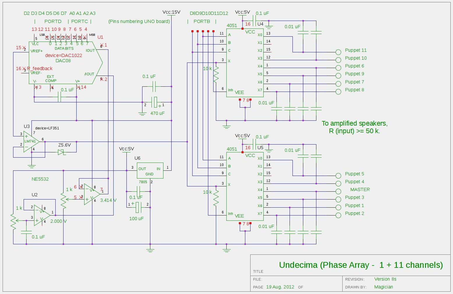
Project gets its name because there is 1 Master channel, and 11 linearly delayed copy of the same audio stream, or Puppets channels, In its essence, this is acoustic Phase Array. As you can see on posted drawings, the heart of the project is 10-bit multiplying (parallel) digital analog converterDAC1022.
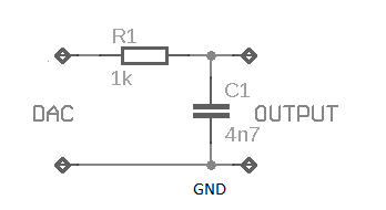
Output of the IC than buffered with OPA and demultiplex`d via two 74HC4051 8-channel analog switches. Outputs of the switches loaded by sampling and hold capacitors 0. 01 uF, to filter out unwanted sampling frequency noise. DAC isconfiguredfor single supply power line. Usually, they recommend to buffer output with / high input impedance / high slew rate / rail to rail / OPA in such configuration.
Which I don`t have, and it costs about half a price of DAC itself, So, this is why I implemented two variable voltage references based on NE5532 and couple of pots. Difference in voltages between tworeferences forms a span . Lower voltage creates an off-set for cheap non rail-to-rail OPA LF351, with adequate slew rate 13 V/usecond.
OPA is heavily loaded by sampling and holdcapacitors, which it sees as connected inparallel at its output, 0. 12 uF overall! To minimize distortion level due overloading of the OPA, span couldn`t be adjust too wide, and preset in current design 1.
414 V, providing exactly 1V RMS output for pure sine wave. I know, that 12 buffers / filters inserted after switches would solve a problem, but idea to solder more than 100 electronics components on a breadboard doesn`t look attractive for me. Software part of the project isstraightforward sample-delay-output function, completely wrapped inside interrupt subroutine.
Main loop is empty. In setup 16 digital pins configured as outputs, 10 of them represent data bus, 5 are address bus and last one is check-point to measure performance withoscilloscope. Timer 2 defines a heartbeat , and fires interrupt every 25 usec, or at 40 kHz. ADC configured to take samples on analog input A5 (first 4 analog pins belong to data bus). Conversion prescaler: 1 MHz, allowing sampling to be completed with fast speed. I left two digital pins D0 and D1 free, as my initial attempts to use them in data bus failed. Arduinoperiodicallyrefuses to reload updates, I`m not sure if it`s Linux problem or on-board USB/RS232 converter.
Each sample, received from the ADC, is shifted left on two bits to skip D0 and D1, and plus one bit more (3 bits left shift overall) to fix imperfection of input preamplifier stage, as NE5532 (again) non rail-to-rail OPA. Look for drawings in Audio Input blog. Measurements show that each channel is receiving a data for about 1 usec window , which is quite fast, nevertheless not fast enough to run 16 channels or to do something else with data before sending them out.
In current hardware implementation the bottle neck is OPA, as DAC has settling time only 500 nanoseconds. 🔗 External reference
Related Circuits
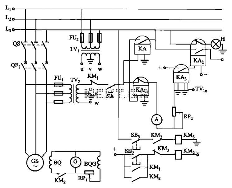
Vehicles from the same period utilize a generator without excitation, which means there is no voltage generator bus, only residual voltage (approximately ten volts). This makes operation relatively simple. It is necessary to wait until the generator speed (frequency)...
This weblog discusses electronic circuit schematics, PCB design, DIY kits, and electronic project diagrams. The subject circuit is a quality preamplifier with a built-in USB DAC designed for the Leachamp power amplifier. The schematic is based on the PCM2902...
You can use this powerful amplifier in any small audio project. It is very small (6.5 x 4.5 cm). It outputs 10W and uses a 9V battery. More: Components List R1: 6 Ohm R2: 220 Ohm R3: nothing R4:...
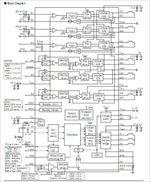
The AN6426NK integrates both speech network and hands-free functionalities. Its well-designed block configuration enables the implementation of a hands-free telephone with a minimal number of components. By Panasonic USA. The AN6426NK is a versatile integrated circuit that combines essential features...

This design circuit for audio amplifiers with DC coupling to the load is not commonly used today, despite its clear advantages. One advantage is the elimination of the need for a second (symmetric) power supply, and another is the...
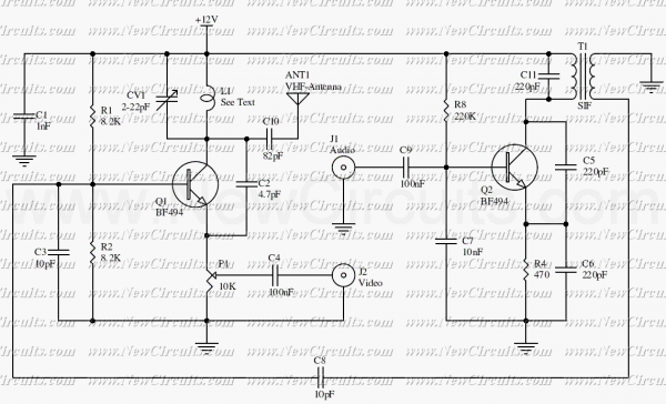
The circuit presented here is a simple audio/video transmitter with a range of 3 to 5 metres. The A/V signal source for the circuit may be a VCR, a satellite receiver or a video game etc. A mixer which...
Warning: include(partials/cookie-banner.php): Failed to open stream: Permission denied in /var/www/html/nextgr/view-circuit.php on line 713
Warning: include(): Failed opening 'partials/cookie-banner.php' for inclusion (include_path='.:/usr/share/php') in /var/www/html/nextgr/view-circuit.php on line 713