
From the same period and vehicle route map
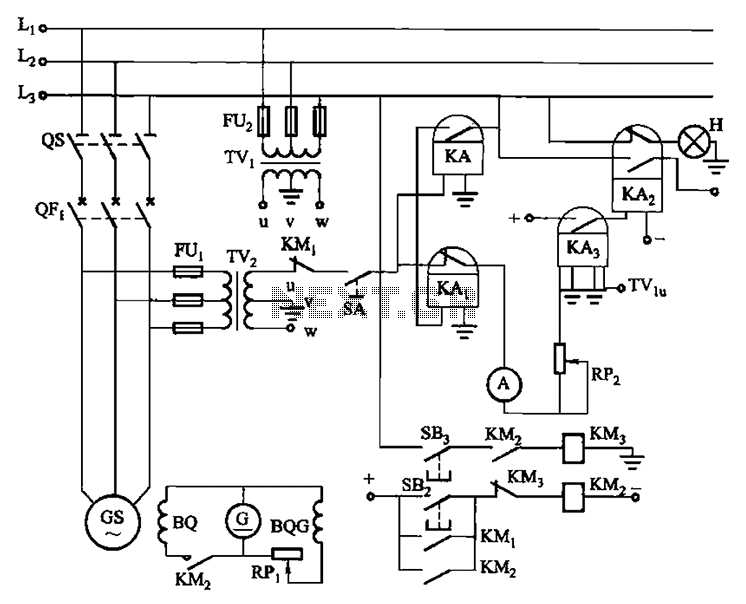
The described system involves a generator that operates without an excitation source, relying solely on residual voltage to function. This configuration is typical in certain vehicle applications from the specified period, emphasizing simplicity in operation. The generator's inherent design allows it to generate a small residual voltage, approximately ten volts, which is adequate for initiating the self-synchronization process once the generator speed approaches that of the grid or another generator.
To achieve synchronization, it is crucial to monitor the generator's rotational speed and ensure it is within a 2.5% variance of the desired operational frequency. Upon reaching this threshold, the main motor switch can be engaged, which connects the generator to the load. The subsequent activation of the Reed magnetic switch is a critical step, as it facilitates the transition to self-synchronization. This process involves the generator adjusting its output to match the frequency of the grid or connected load, allowing for seamless integration into the electrical system.
The electrical schematic for this system would typically include the generator, the main motor switch, and the Reed magnetic switch, along with appropriate wiring and control elements to manage the synchronization process. The generator would be depicted with its residual voltage output, and the control circuitry would illustrate how the switches interact to achieve the desired operational state. Proper attention to the specifications of each component is essential to ensure reliable performance and stability during operation.And vehicles from the same period, the generator without excitation, no voltage generator bus, only the residual voltage (approximately ten volts), so operation is relatively s imple. Just wait and when the generator speed (frequency) rose nearly been put into operation a generator (or grid) of the speed (or frequency rate) value (which can be the difference between 2. 5%, not necessarily exactly equal) to be closed concurrently motor main switch, then quickly put Reed magnetic, it will cause the generator to be quickly and self-synchronization system is to pull people.
From the same period and vehicle wiring shown in Figure 7-9; the secondary wiring is shown
Related Circuits

Amplify a MG811 CO2 sensor to a range readable by an ATMEGA2560 (0-5V). Other analog sensors are in use, so it is preferred not to change the reference voltage on the ATmega. A module that scales the signal has...
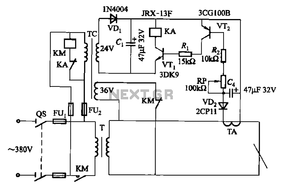
The AC arc welding machine's transistor load path for the power from the second circuit is illustrated. The figure shows a current transformer with a core cross-section of 25 mm². The transformer has a primary winding with a certain...
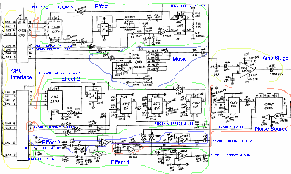
This tutorial provides a comprehensive guide to creating a discrete sound emulation for the Phoenix game. It covers the steps required to interface the discrete sound code with the driver and how to transcribe the schematic into discrete code,...
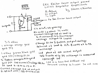
The following experiment demonstrates how Mr. Steven successfully extracted free energy from air using his home-built secondary exciter coil tower. He utilized this energy to power a small LM317 power supply unit. During the process, he hand-wound his coils...

The E1T tube has been a part of the family for many years. It was likely brought home by my father, who worked at the Shell laboratory in Rotterdam, or purchased from surplus shops we visited on Saturday mornings...
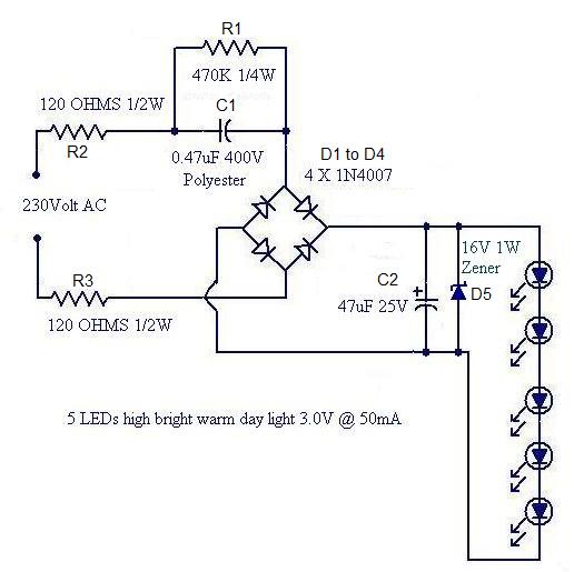
Convert a used CFL into a power-saving LED lamp circuit that consumes only 50mA. This gadget can be used in applications like a night light, table lamp, etc. The project involves redesigning a compact fluorescent lamp (CFL) to function as...