
Understanding FM transmitter circuit

The Wireless FM Transmitter circuit utilizes an electret microphone as the primary audio input source. The electret microphone converts sound waves into electrical signals by varying its output current in response to sound pressure levels. The specified current of 200 µA, with a variation of ±3 µA, causes a corresponding change in voltage across R1, which is a critical component in determining the signal level fed into the circuit.
When sound waves strike the microphone, the resulting change in current through R1 alters the voltage across the microphone, effectively modulating the audio signal. This modulated signal is then coupled through capacitor C1, which blocks any DC component while allowing the AC audio signal to pass through to the base of the transistor. The transistor acts as an amplifier, with its base biased at approximately 2V through resistors R2 and R3, facilitating proper operation within the active region.
The voltage across R4 is influenced by the voltage at the base of the transistor, which changes in response to the audio signal. When no signal is present, the voltage across R4 is determined by the biasing conditions, specifically Vb - 0.7V, resulting in a steady-state voltage of 1.3V. As the audio signal modulates the base voltage, the current through R4 changes, which subsequently affects the tank circuit's behavior.
The tank circuit, comprising an inductor and capacitor, is responsible for determining the transmission frequency. The modulation of the base voltage influences the tank circuit's resonant frequency, thus allowing for frequency modulation. In this context, it is important to note that true frequency modulation requires a change in the frequency of the carrier wave, which is achieved through variations in the tank circuit's parameters, rather than merely amplitude changes.
Capacitor C3's role in the circuit is critical; it may serve to stabilize the collector-emitter voltage or help filter high-frequency noise. It can also function as a bypass capacitor, improving the performance of the circuit by providing a low impedance path for AC signals while maintaining a stable DC voltage. Bypass capacitors are typically connected to ground to ensure they effectively filter out unwanted AC components from the power supply, thus enhancing the overall stability and performance of the transmitter circuit.
Understanding these components and their interactions is essential for grasping the operation of the Wireless FM Transmitter and ensuring effective modulation and transmission of audio signals.Wireless FM Transmitter. The site has some explanation on how the circuit works, however I`m not sure about a few things, including the electret mic & how the frequency modulation takes place. The electret microphone has a current of 200uA which changes by +- 3 uA depending on sound waves. This sets the voltage across R1 to 2V and the voltage acro ss the mic to 4 volts. As the sound hits the mic the current through R1 increases slightly reducing the voltage across the mic. Is that what is happening This changing voltage is passed on by the coupling cap, C1 to the base of the transistor, which is biased by R2 & R3 to approx 2V.
The voltage across R4 with no signal on the mic will be Vb - 0. 7 (drop across vbe), 1. 3 volts. As the voltage at b changes R4 will change by the same amount. This change in voltage is seen at the base of the tank circuit. And the signals voltage is increased/decreased. Isn`t this what happens in AM As wouldn`t the capacitance need to change in order to get Frequency modulation And if it was amplitude modulation occuring in the FM spectrum, then how would a radio receiver be able to demodulate the signal At this point I`m not sure what is happening at the capacitor C3, what is that doing Is it holding CE at a fixed voltage And is it along with capacitor C2 considered a bypass capacitor Or do bypass capacitors need to be connected to ground 🔗 External reference
Related Circuits
A gas leak detector circuit that detects the leakage of LPG gas and alerts the user through audio-visual indications. The circuit operates off a 9V PP3 battery. A Zener diode is used to convert 9V into 5V DC to...
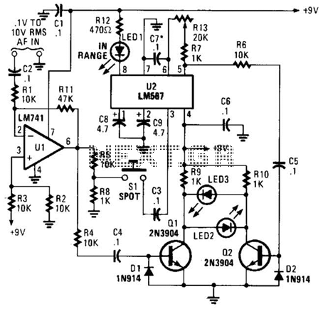
This meter is unique as it does not utilize a D'Arsonval movement or digital display for frequency readings. Instead, the measured frequency is indicated on a hand-calibrated dial. Any audio signal applied to the circuit is amplified by U1,...
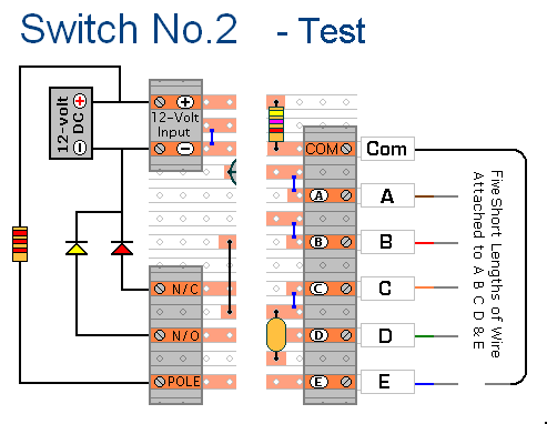
The prototype of Keypad Switch No. 2 was constructed using only the stripboard layout as a reference. If the layout has been accurately reproduced, a functional circuit will result. Once the layout is confirmed to be correct and a...
The Reaction Capability Tester is utilized to assess and enhance an individual's quick-response abilities. It features various designs, with the depicted model comprising a CD4017 decimal counter and a light-emitting diode (LED). The construction of the Reaction Capability Tester...
A remote control light switch designed to fit into an existing light switch panel requires a 3.3V DC power supply for its electronics. However, the panel contains only two wires: one live wire and one wire that connects to...
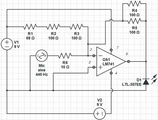
Red = V+, Black = V-, Green = GND, Yellow = Mic Input, Orange = LED Output. The op-amp used is an LM741, which is intended to adjust the peak brightness of the LED based on the ambient sound...