
digital logic How does an AND gate behave in this situation

In an electronic circuit utilizing an AND gate, the operation is contingent upon the states of the input signals. This type of gate requires both inputs to be in a high state (logic level '1') for the output to also be high. When both switches connected to the inputs of the AND gate are closed, the circuit allows current to flow, thereby providing a high signal to the AND gate's inputs. Consequently, the output will also reflect a high state.
Conversely, if either or both of the switches are open, the inputs to the AND gate may not have defined voltage levels. In such cases, the output becomes indeterminate, as the AND gate cannot reliably process undefined or floating input signals. This results in an output that may fluctuate or remain at a low state (logic level '0'), which can lead to erratic behavior in the overall circuit operation.
To ensure reliable operation, it is advisable to implement pull-up or pull-down resistors on the inputs of the AND gate. Pull-up resistors can ensure that the input defaults to a high state when the switches are open, while pull-down resistors can maintain a low state under the same conditions. This practice stabilizes the input levels and mitigates the risk of undefined states, thereby enhancing the circuit's performance and predictability.The AND output will be high with both switches closed. However, nothing is guaranteeing the level of the inputs when the switches are open, so the result could be anything. Olin Lathrop Mar 6 `13 at 19:58 🔗 External reference
Related Circuits

The AD9835 combines the Numerical Controlled Oscillator (NCO), COS Look-Up Table, Frequency and Phase Modulators, and a Digital-to-Analog Converter on a single integrated circuit. With more easy words you can say that this circuit is an oscillator where the...
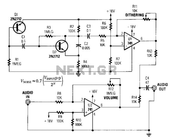
By introducing a small amount of noise to a signal intended for digitization (approximately 0.7 bits), where n represents the number of bits, for instance, an 8-bit signal with a peak-to-peak voltage of 2 V would result in a...
The project began as a simple variac (variable autotransformer) and electrical outlet mounted on a wooden block. Eventually, it was housed in the case of an old audio signal generator for improved safety and aesthetics. A 0-250VAC analog meter...
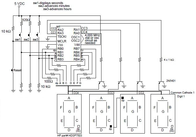
A digital clock project utilizing the PIC16C54 microcontroller can be constructed using the provided circuit diagram. This electronic project features a time-of-day clock that includes four seven-segment LED displays and three input switches. Additionally, there is a reset switch...
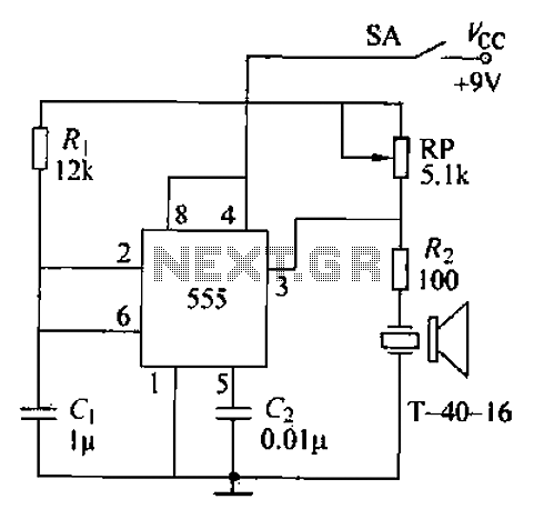
The circuit comprises an ultrasonic transmitter and a T-4 0-16 555 timer circuit. By adjusting the potentiometer RP, the frequency of the oscillation circuit can be modified. The circuit emits ultrasonic signals at a frequency of 40 kHz, with...
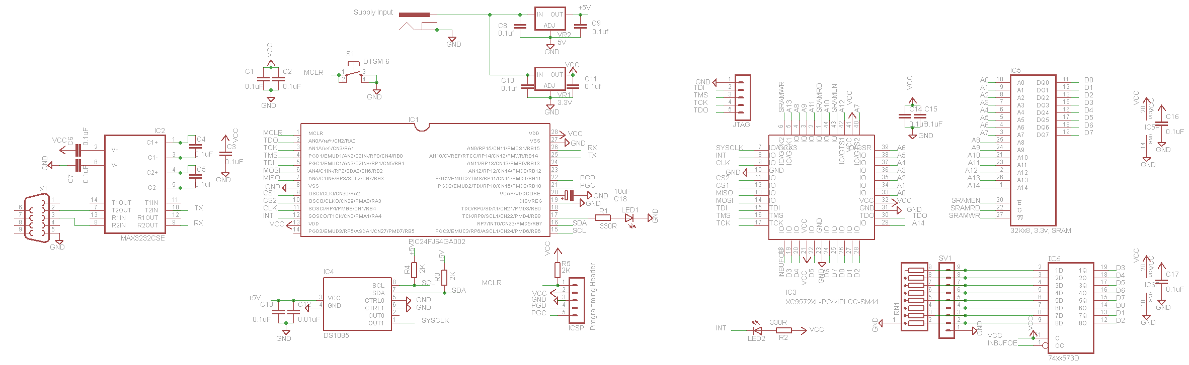
Complex programmable logic devices (CPLDs) contain the building blocks for hundreds of 7400-series logic ICs. Complete circuits can be designed on a PC and then uploaded to a CPLD for instant implementation. CPLDs are integrated circuits that provide a versatile...