
Universal-battery-charger

When power is applied to the circuit, SCR1 is off, resulting in no bias current path to ground; thus, LM317 operates as a current regulator. The LM317 is connected to the battery through steering diode D1, limiting resistor R1, and bias resistor R2. The steering diode prevents the battery from discharging through the LED and the SCR when power is removed from the circuit. As the battery charges, the voltage across trip-point potentiometer R5 increases, eventually turning on the SCR. At this point, current from the regulator can flow to ground, allowing the regulator to function in voltage mode. When the SCR is activated, it also provides LED1 with a path to ground through resistor R3. Consequently, when LED1 is illuminated, the circuit is in voltage-regulating mode; when LED1 is off, the circuit operates in current-regulating mode.
The circuit in question employs a Silicon Controlled Rectifier (SCR) and an LM317 voltage regulator to manage the charging and discharging of a battery. Initially, when power is supplied, SCR1 remains in the off state, which means that there is no current flowing to ground. This allows the LM317 to function as a current regulator, controlling the charging current to the battery.
The connection of the LM317 to the battery is facilitated by several components: a steering diode (D1), a limiting resistor (R1), and a bias resistor (R2). The purpose of the steering diode is critical; it ensures that when the power supply is removed, the battery does not discharge back through the LED and SCR, thereby protecting the circuit and preserving battery life.
As the battery continues to charge, the voltage across the trip-point potentiometer (R5) rises. Once this voltage reaches a predetermined threshold, it triggers the SCR to turn on. This action allows current from the LM317 to flow to ground, transitioning the regulator from current mode to voltage mode.
In this voltage-regulating mode, the SCR provides a pathway for current to flow through LED1 via resistor R3. The status of LED1 serves as an indicator of the circuit's operational mode: when LED1 is lit, it signifies that the circuit is regulating voltage; conversely, when LED1 is off, it indicates that the circuit is regulating current. This dual-mode operation is essential for effectively managing the charging process of the battery, ensuring optimal performance and longevity.
Overall, this circuit design showcases an efficient method for battery management, utilizing the characteristics of both the LM317 and SCR to create a versatile charging system that adapts to the state of the battery.When power is applied to the circuit, SCRl is off, so there is no bias-current path to ground; thus, L~317 acts as a current regulator. The LM317 is umnected to the battery through steering diode Dl, limiting resistor Rl, and bias resistor R2.
The steering diode prevents the battery from discharging through the LED and the SCR when power is removed from the circuit. As the battery charges, the voltage across trip-point potentiometer R5 rises, and at some point, turns on the SCR. Then, current from the regulator can flow to ground, so the regulator now functions in the voltage mode.
When the SCR turns on, it also provides LEDl with a path to ground through R3. So, when LEDl is on, the circuit is in the voltage-regulating mode; when LEDl is off, the circuit is in the current- regulating mode.
Related Circuits
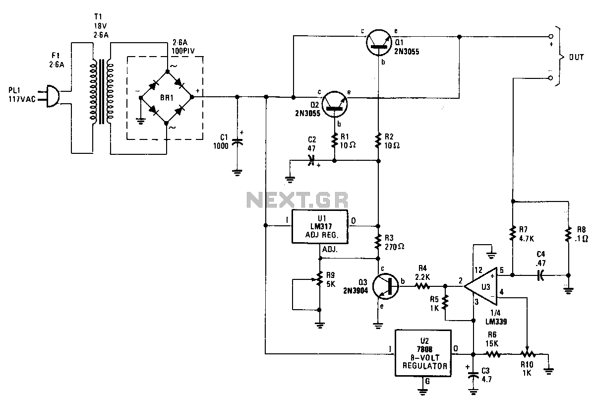
The charger's output voltage is adjustable and regulated, featuring an adjustable constant-current charging circuit that facilitates compatibility with most NiCad batteries. It is capable of charging a single cell or multiple series-connected cells, with a maximum voltage of 18...