
Universal-battery-charger

The charger's output voltage is adjustable and regulated, featuring an adjustable constant-current charging circuit that facilitates compatibility with most NiCad batteries. It is capable of charging a single cell or multiple series-connected cells, with a maximum voltage of 18 V. Power transistors Q1 and Q2 are configured as series regulators to manage the output voltage and charge current of the battery charger. An LM317 adjustable voltage regulator provides the drive signal to the bases of power transistors Q1 and Q2. A potentiometer (R9) is utilized to set the output voltage level. A current-sampling resistor (R8), rated at 0.1 ohms and 5 watts, is connected between the negative output lead and circuit ground. For every amp of charging current that flows through R8, a voltage of 100 mV is developed across it. This voltage is then fed to one input of comparator U3, while the other input is connected to a variable resistor (R10). As the charging voltage across the battery begins to decline, the current through R8 decreases, leading to a reduction in the voltage at pin 5 of U3. Consequently, the output of the comparator decreases, turning off Q3, which completes the feedback loop to regulate the charging current of the battery. The charging current can be adjusted by modifying R10 to achieve the desired current level, while the circuit's output voltage is determined by R9.
The described circuit integrates several key components to achieve its functionality. The adjustable output voltage is a significant feature, allowing for flexibility in charging various battery configurations, specifically NiCad batteries. The use of power transistors Q1 and Q2 as series regulators is critical in maintaining the desired voltage and current levels during the charging process.
The LM317 voltage regulator is pivotal in this circuit, as it provides a stable reference voltage to control the base of the power transistors. This allows for precise adjustments to the output voltage based on the needs of the battery being charged. The potentiometer R9 is essential for setting the output voltage level, enabling the user to tailor the charging process to specific battery requirements.
Current monitoring is achieved through the current-sampling resistor R8, which is strategically placed to measure the charging current. The voltage drop across R8 provides a feedback mechanism that is essential for regulating the charging process. The comparator U3 plays a crucial role in this feedback loop, ensuring that the charging current is adjusted dynamically based on the battery's state of charge. The variable resistor R10 allows the user to set the desired charging current, giving further control over the charging process.
Overall, this circuit exemplifies a well-designed battery charger capable of efficiently managing the charging of NiCad batteries through adjustable voltage and current regulation, ensuring optimal performance and longevity of the batteries.The charger"s output voltage is adjustable and regulated, and has an adjustable constant-current charging circuit that makes it easy to use with most NiCad batteries. The charger can charge a single cell or a number of series-conoected cells up to a maximum of 18 V. Power transistors Ql and Q2 are conoected as series regulators to control the battery charger"s output voltage and charge-current rate.
An LM317 adjustable voltage regulator supplies the drive signal to the bases of power transistors Ql and Q2. Potentiometer R9 sets the output-voltage level. A current-sampling resistor, R8 (a 0.1-!J, 5-W unit), is conoected between the negative output lead and circuit ground. For each amp of charging that flows through R8, a 100 mV output is developed across it. The voltage developed across RS is fed to one input of comparator U3. The other input of the comparator is connected to variable resistor RIO. As the charging voltage across the battery begins to drop, the current through RS decreases. Then the voltage feeding pin 5 of U3 decreases, and the comparator output follows, turning Q3 back off, which completes the signal"s circular path to regulate the battery"s charging current.
The charging current can be set by adjusting RlO for the desired current. The circuit"s output voltage is set by R9.
Related Circuits
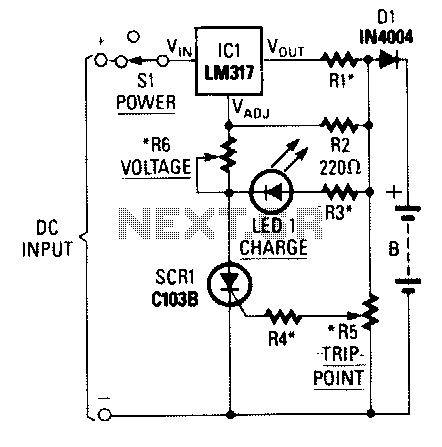
When power is applied to the circuit, SCR1 is off, resulting in no bias current path to ground; thus, LM317 operates as a current regulator. The LM317 is connected to the battery through steering diode D1, limiting resistor R1,...