
universal battery charger schematic

The described charger circuit operates effectively for charging a variety of battery types, including both single cells and series-connected configurations, ensuring flexibility in application. The use of power transistors Q1 and Q2 in a series regulator arrangement allows for efficient control over the output voltage and current, which is crucial for maintaining battery health and optimizing charging efficiency.
The LM-317 adjustable voltage regulator plays a pivotal role in providing a stable drive signal to the power transistors, allowing for fine-tuning of the output voltage. The incorporation of potentiometer R9 facilitates user adjustments to the output voltage level, accommodating different battery specifications.
The current sensing mechanism implemented with resistor R8 is vital for monitoring the charging current. By generating a 100mV signal for each ampere of current, it enables accurate feedback to the comparator U3, which is essential for maintaining the desired charging conditions. The arrangement of the comparator with variable resistor R10 allows for additional customization, ensuring that the circuit can adapt to various charging scenarios.
The feedback loop involving comparator U3 and transistor Q3 is a critical feature of this charger design. As the battery voltage drops, the charging current decreases, leading to a proportional response in the control circuit. This dynamic regulation process ensures that the battery is charged safely and efficiently, preventing overcharging and extending the battery's lifespan.
Overall, this charger circuit exemplifies a robust design that integrates essential components for effective battery management, providing a reliable solution for charging applications in various electronic systems.The charger can charge a single cell or a number of series-connected cells up to a maximum of 18V. Power transistors Q1 and Q2 are connected as series regulators to control the battery charger`s output voltage and charge-current rate. An LM-317 adjustable voltage regulator supplies the drive signal to the bases of power transistor Q1 and Q2.
Potensiometer R9 sets the output-voltage level. A current sampling resistor, R8 (a 0. 1 ohm/5W unit), is connected between the negative output lead and circuit ground. For each amp of charging current that flows through R8, a 100mV output is developed across it. The voltage developed across R8 is fed to one input of comparator U3. The other input of the comparator is connected to variable resistor R10. As the charging voltage across the battery begins to drop, the current through R8 decrease. Then the voltage feeding pin 5 of U3 decreases, and the comparator output follows, turning Q3 back off, which completes the signal`s circular path to regulate the battery`s charging current. 🔗 External reference
Related Circuits
The induction coil detects the magnetic field flux during phone calls, amplifies the signal, and triggers the LED. These circuits are designed for the phone to rest on the pickup coil. The electromotive force (emf) from the bell electromagnets...
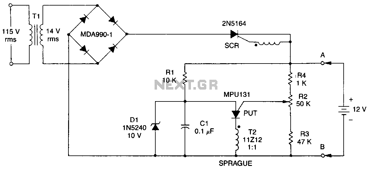
This battery charger operates by continuously charging at maximum current, gradually tapering off as the battery approaches full voltage. The full load current from the supply transformer and rectifier section is 4.4A. The current decreases to 4A at 13.5V,...
Nokia BL-4C and BL-5C are 3.7V, 700-1000mAh (various) lithium-ion batteries that have three terminals. These terminals include a positive terminal, a ground, and a BSI (Battery Status Indicator) terminal, which presents a fixed resistance value that needs to be...
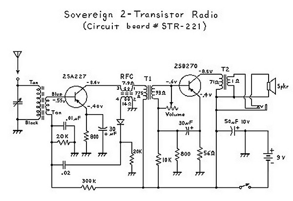
An analysis of certain radios reveals the impressive engineering by Japanese designers, particularly in creating a radio capable of driving a speaker with only two transistors. The first transistor (Q1) serves a dual function; it operates as an RF...
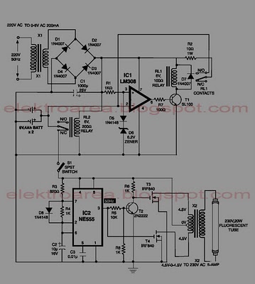
This circuit is an IC-controlled emergency light system. It automatically switches on the light during a mains failure and includes a battery charger with overcharge protection. When the mains power is absent, relay RL2 is in a de-energized state,...
A short-circuit-proof battery charger provides an average charging current of approximately 8 A to a 12-V lead/acid storage battery. The charger circuit has the additional advantage of being unaffected and undamaged by incorrect battery connections. With an input voltage...