
UNIVERSAL TEST OSCILLATOR

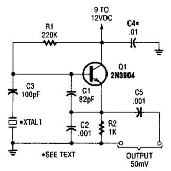
The Pierce oscillator circuit is a popular configuration for generating stable sine wave signals, particularly in RF applications. In this configuration, the crystal acts as a frequency-determining element, providing a high degree of stability and precision to the output frequency. The placement of the crystal in the feedback loop between the base and collector of the transistor Q1 ensures that the oscillator can sustain oscillations at the desired frequency.
The use of a 2.5 mH RF choke in place of a tuned collector circuit is critical for impedance matching and minimizing loading effects on the oscillator. The choke serves to block RF signals while allowing DC biasing to the transistor, which is essential for proper operation. The choke's inductance value must be chosen carefully to ensure that it does not resonate with the crystal at the intended operating frequencies.
The oscillator's frequency range from 400 kHz to 20 MHz is determined by the characteristics of the crystal used. Fundamental frequency crystals are preferred for their performance, as they provide a more predictable oscillation frequency. In contrast, third overtone crystals may still function but will do so at the fundamental frequency, which may not be suitable for applications requiring higher frequencies.
Capacitor C1 plays a vital role in tuning the oscillator's frequency. For applications operating at 1 MHz and above, the specified value of C1 is adequate. However, for lower frequency applications, increasing the capacitance to 330 pF is recommended to maintain stable oscillation and ensure that the circuit operates effectively within the desired frequency range.
Overall, the Pierce oscillator configuration with a crystal in the feedback path is a robust solution for generating precise frequencies in electronic circuits, particularly in communication and signal processing applications. Proper selection of components and careful design considerations are essential for achieving optimal performance.Crystal is in feedback path of Pierce oscillator, between base and collector of al, with 2.5-mH RF choke in place of tuned collector circuit. Oscillator works from 400 kHz to 20 MHz, depending on crystal. Designed for fundamental crystals; third overtone types will oscillate but at fun-damental. Value of 01 is for 1 MHz and higher; increase to 330 pF for l.. 🔗 External reference
Related Circuits
The SI2171 is a sub-package of the SI2170. For further details, please refer to the SI2170 description. The datasheet for the SI2171 can be downloaded from the link provided below. By Silicon Laboratories. The SI2171 is a versatile integrated circuit...
This webpage outlines the radio transmitter unit that was part of the Cirrus One rocket mission in April 2001. The transmitter was included as a payload due to concerns about recovery challenges if the rocket drifted far downrange after...
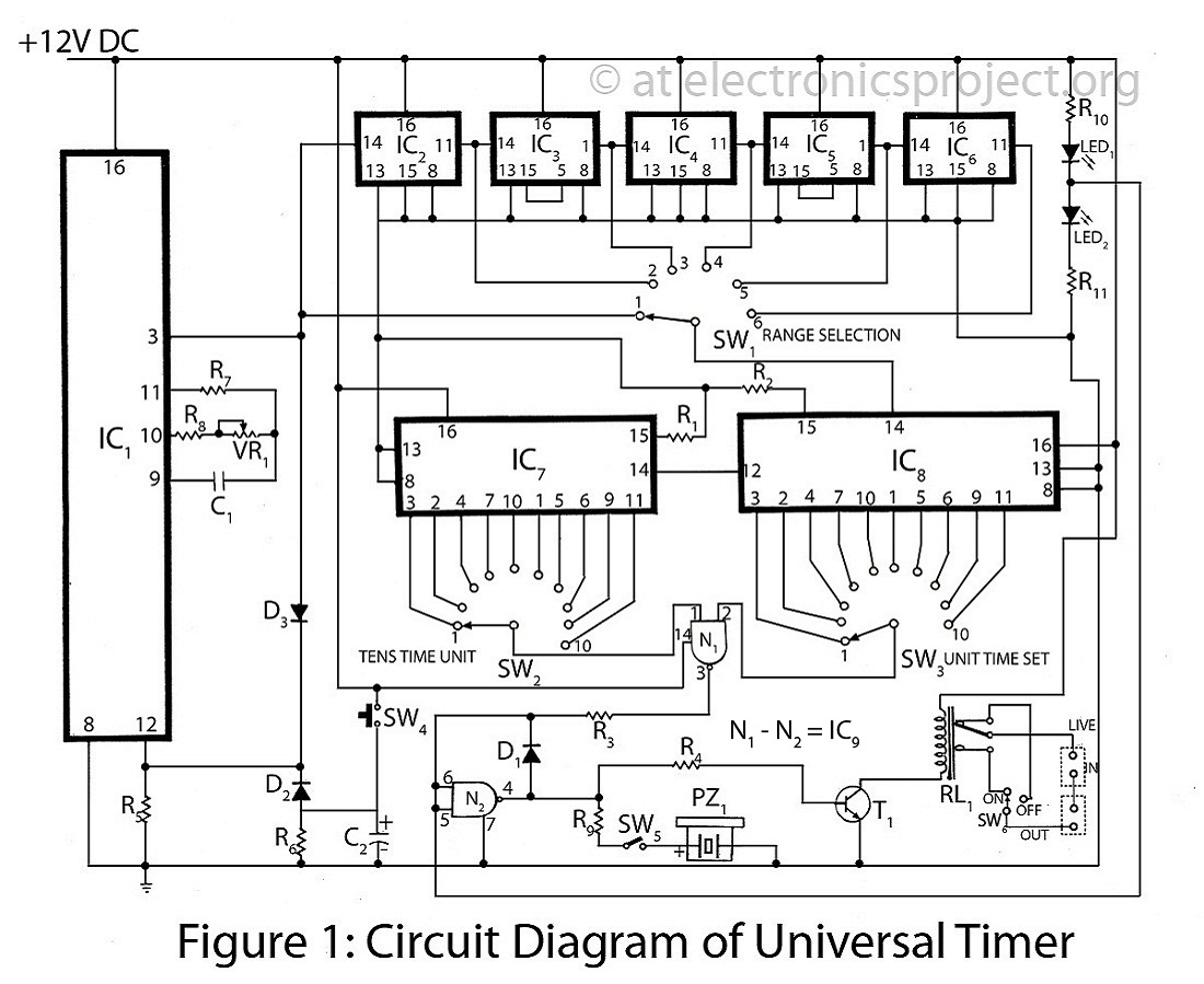
The Universal Timer is a highly versatile timer project that accommodates a wide range of time periods, from 1/10th of a second to 100 hours. This circuit diagram includes a comprehensive description of various timer circuits associated with the...
This is a simple Colpitts crystal oscillator for 1 to 20 MHz, which can be easily constructed from spare parts, provided that a crystal is available. The Colpitts oscillator is a type of electronic oscillator that utilizes a combination of...
The square wave oscillator does not necessarily need to be a 555 timer; it can also be implemented using a ring oscillator with inverters. However, when utilizing 4000 series CMOS logic, the negative output voltage generated may have limited...
Using a single 555 Timer IC and a small transformer to generate a high voltage, this circuit will test zener diodes of voltage ratings up to 50VDC. The 555 timer is used in the astable mode, the output at...