
ADT70 platinum resistance temperature measurement circuit

The AD170 is a precision temperature measurement device that is particularly well-suited for applications requiring high accuracy and stability over a wide temperature range. The integration of a voltage source, current source, and amplifier within the ADT70 simplifies the design of the temperature measurement circuit, minimizing the need for additional external components. This integration allows for a more compact and efficient design, reducing potential points of failure and enhancing reliability.
In the described PRTD configuration, the 4-wire setup is crucial for eliminating errors due to lead resistance, which can significantly affect measurement accuracy in lower resistance sensors. By using two wires for the measurement and two for the current supply, the circuit can effectively cancel out the resistance of the lead wires, ensuring that the measurement reflects only the resistance of the platinum sensor itself.
The reference resistor R is carefully selected to match the output current of the current source, ensuring that the system operates within its specified parameters. The outputs OUTA and OUTB are connected to the instrumentation amplifier, which is designed to amplify small differential signals. The instrumentation amplifier's high input impedance prevents loading of the sensor and allows for accurate signal processing.
The gain of the instrumentation amplifier is adjustable via the external resistor Rc, providing flexibility in the circuit design to accommodate various measurement ranges and sensitivities. This feature is particularly advantageous in applications where different temperature ranges may need to be monitored without redesigning the entire circuit.
Overall, the AD170 and its associated circuitry represent a robust solution for precision temperature measurement, combining ease of use with high performance, making it suitable for a variety of industrial and laboratory applications.AD170 basic electrical parameters are as follows: temperature coefficient of 25ppm/C, temperature measurement accuracy of l, the maximum temperature in the range of a 200 ~ + I OOOqC, the power supply + 5v or t5v, operating temperature range of -40- + 125 C. ( 1) PRTD platinum resistance temperature measurement circuit. Since ADT70 internal integration of the voltage source, a current source and amplifier, because this use it as a measuring temperature, the external circuit is very simple, as shown in Figure 1-47 is ADT70 platinum RTD temperature measurement circuit. PRTD 4-wire (2-wire one end respectively connected to + INIA,/OUTB, 2 lines are grounded and the other end of the op amplifier of ?
feet) platinum resistance thermometer, R is the reference resistor, matching current source output current, OUTA,/OUTB are applied to the reference resistance test, instrumentation amplifier - UNIA and platinum resistance, the instrumentation amplifier + on INIA, platinum resistance thermometer output signal simultaneously. after the op amp and instrumentation amplifier amplifies the output pin ? instrument gain of the amplifier by the variable external resistor Rc decision G 49. 9kfl/Rc
Related Circuits
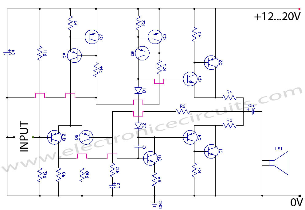
Discrete Class AB Transistor Audio Power Amplifier Circuit Diagram. This is a Class AB transistor power amplifier. It is a simple amplifier to... A Class AB transistor audio power amplifier is designed to provide high-quality amplification for audio signals while...
The USB charger power supply is designed for use in MP3 and MP4 chargers. It accepts an input of AC 160-240V at 50/60Hz and has a rated output of DC 5V at 250mA. For applications requiring a long-term higher...
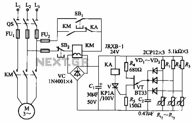
The thyristor control circuit includes a bridge circuit designed to regulate the temperature in the contactor coil KM, along with a secondary winding that functions as a power protection device. It comprises a thermistor (R:., Rt3) and a resistor...
This timer is designed for individuals seeking to achieve a tan while minimizing excessive exposure to sunlight. A rotary switch adjusts the timer based on six classified photo-types. A photoresistor modifies the preset time according to the brightness of...
All car batteries require a 12V battery charger, which also applies to marine, RV, and power sports batteries. The high-efficiency lead-acid batteries available today necessitate more effective charging techniques. The battery charger is a crucial tool for prolonging battery...
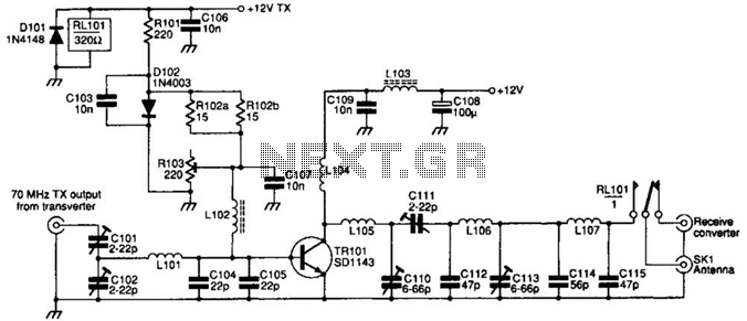
The SD1143 transistor offers a gain of approximately 14 dB in this circuit. Its design takes advantage of the fact that a 175-MHz device exhibits significantly higher gain when operated at lower frequencies. The amplifier was initially intended for...