
Up-Controlled Negative Voltage Converter

This circuit employs a 74F374 flip-flop to generate a square wave output, which serves as the primary signal for creating a variable negative voltage. The flip-flop's output is AC coupled to a rectifier circuit, which converts the AC signal into a DC voltage. The rectifier typically consists of diodes arranged in a configuration that allows for the effective conversion of the square wave into a usable DC level, which can be further smoothed using capacitors to reduce ripple.
The microprocessor (uP) plays a crucial role in this circuit by providing the clock signal necessary for the flip-flop operation. Additionally, data from the processor bus is utilized to control the timing and loading of the flip-flop, allowing for precise adjustments to the output voltage level. The load signal from the microprocessor enables the system to dictate when the flip-flop should latch the input data, effectively controlling the duty cycle of the square wave output and consequently the average DC voltage produced.
To achieve variable contrast control for the LCD display, the circuit can be designed with feedback mechanisms that monitor the output voltage level. This feedback can be processed by the microprocessor to adjust the load signal dynamically, ensuring that the desired contrast level is maintained across varying conditions and display requirements. Components such as operational amplifiers may also be incorporated to further refine the output voltage characteristics, ensuring stability and responsiveness to user inputs or system changes.
Overall, this circuit provides an efficient method for generating a variable negative voltage, enhancing the functionality and user experience of LCD displays through effective contrast control. This circuit was used to produce a variable negative voltage for contrast control of an LCD displa y. A 74F374 generates a square wave that is ac coupled to a rectifier and load. By using the uP clock and data from the processor bus, and properly timed load signal, the dc level generated can be controlled by the uP.
Related Circuits
The LT3465/LT3465A are step-up DC/DC converters designed to drive up to six LEDs in series from a Li-Ion cell. Series connection of the LEDs provides identical LED currents and eliminates the need for ballast resistors. These devices integrate the...
This circuit is intended to provide good square waves converting a sine wave picked up from an existing generator. Its main feature consists in the fact that no power source is needed: thus it can be simply connected between...
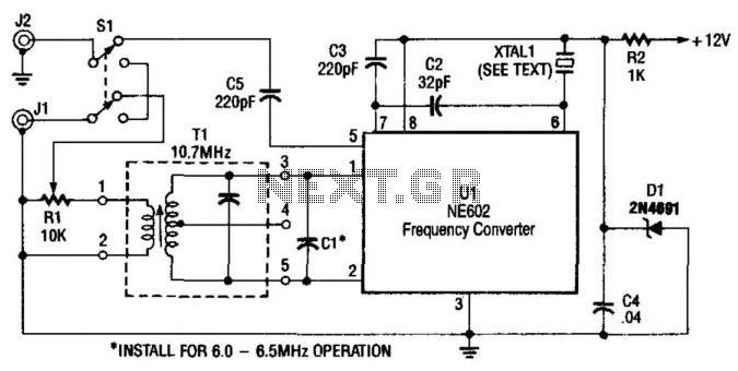
A Signetics NE602 is utilized in this converter to tune the frequency range of 9.5 to 9.8 MHz. An AM car radio functions as a tunable intermediate frequency (IF) amplifier, with the output being taken from J2, the auto...
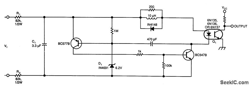
This circuit below illustrates a simple voltage-controlled oscillator (VCO) connected to instrumentation via an optoisolator. The voltage-controlled oscillator (VCO) circuit operates by generating a periodic waveform whose frequency is determined by an input control voltage. The primary components of this...
This type of converter is used to convert analog voltage to its corresponding digital output. The function of the analog-to-digital converter is exactly opposite to that of a digital-to-analog converter. Like a digital-to-analog converter, an analog-to-digital converter is also...
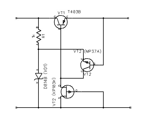
The schematic diagram originates from a voltage regulator circuit utilizing a Field Effect Transistor (FET) power supply. This circuit features a feedback mechanism involving the FET VT3, which functions as a dynamic load for transistor VT2. This configuration enhances...