
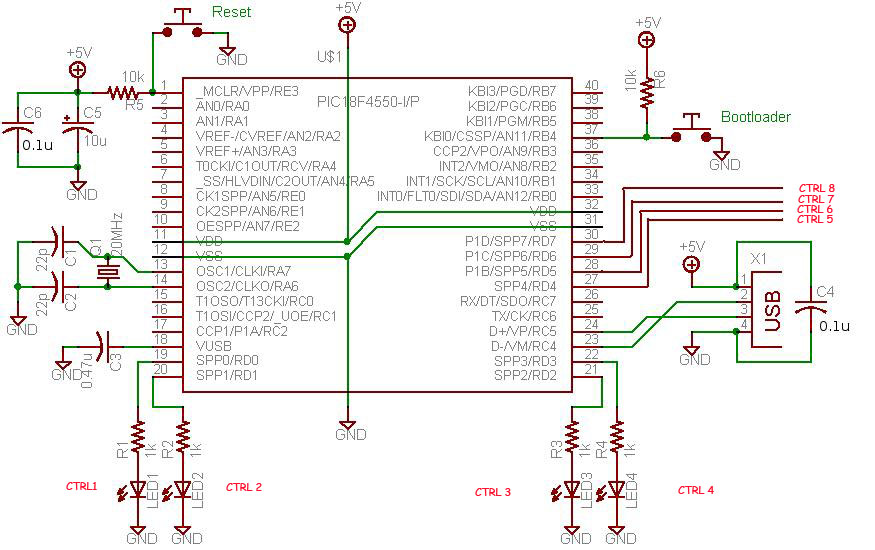
USB AVR programmer
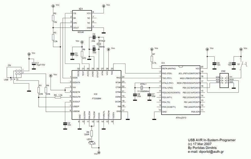
The circuit design integrates an FT232BM USB to Serial converter, which facilitates the communication between the ATtiny2313 microcontroller and the PC through a USB interface. The FT232BM chip is responsible for handling the USB protocol and converting the USB signals to serial RS-232 signals that the ATtiny2313 can understand. The schematic includes the necessary connections for power, data transmission, and control signals, ensuring proper operation of the programming process.
Powering the circuit is achieved through the USB-B connector (CN1), which connects to the PC. This connector provides the necessary +5V supply to the circuit, with the S1 switch allowing the user to control power delivery to the target AVR. The 6-pin connector (CN2) is configured to interface directly with the programming pins of the AVR, allowing for seamless programming and debugging.
The inclusion of the serial EEPROM (IC1) provides additional functionality, enabling the storage of user-defined settings and the identification of the programmer when connected to a PC. This feature allows for customization of the programmer's name and firmware version, enhancing user experience and providing essential information during operation.
LED D1 serves as an indicator, providing visual feedback to the user regarding data transmission and reception activities. This feature is critical for troubleshooting and ensuring that the communication between the programmer and the PC is functioning correctly.
In summary, this modified AVR In-System Programmer circuit effectively utilizes the FT232BM chip to convert USB signals to RS-232 levels, enabling efficient programming of AVR microcontrollers while maintaining user-friendly features such as power control, customization options, and visual feedback. The design ensures that the circuit operates within the current limitations of USB power supplies, making it a practical solution for modern programming needs.Nowadays, USB is the most popular connection connection between PC and peripherals such as AVR programmers, printers, scanners etc. For that reason I had to modify my old serial AVR In-System-Programmer (ISP) to work with USB connection.
You can say, "use a USB to Serial adaptor to connect your AVR ISP with your PC". Yes, that could be a solution but it would cost me more money than a singe FT232BM chip because I had to include an USB to RS232 adaptor and a power supply for my programmer. (almost 30). So, the solution was to replace the two transistors, that were used to adapt the RS-232 voltage levels to TTL voltage levels, with a USB to RS-232 chip such as FT-232BM.
Following the schematic diagramthat I read in the FT232BM manual I made the connections between ATtiny2313 and FT232BM. The FT232BM requires a few and ordinary components to work. When you connect this circuit to your PC you will see the message " a new hardware was found" and then the factory name of FT232BM.
IC1 is a serial EEPROM that used to store user`s settings. So, you can rename this programmer to be appeared as "AVR In-System-Programmer" or "MyAVR programmer". Furthermore, you can add the firmware version of your circuit. Of cource, you can bypass this component because it`s optional. I saw that the programmer works with orwithout this EEPROM. Anyway, FTDI suggests you to use this EEPROM. Led D1 flasheswhen data are transmitted or received by FT232BM. CN1 is a USB-B connector and CN2 is a 6-pin connector to your target AVR (it is connected to the AVR to be programmed).
The S1 switch is used to supply your target circuit with +5V from the USB connector of your PC. In this case you won`t need any additional power supply for your target circuit. Consider that a single USB port can supply up to 500mA current. You should not exceed this current limitation including the current that needs your AVR programmer too. 🔗 External reference
Related Circuits
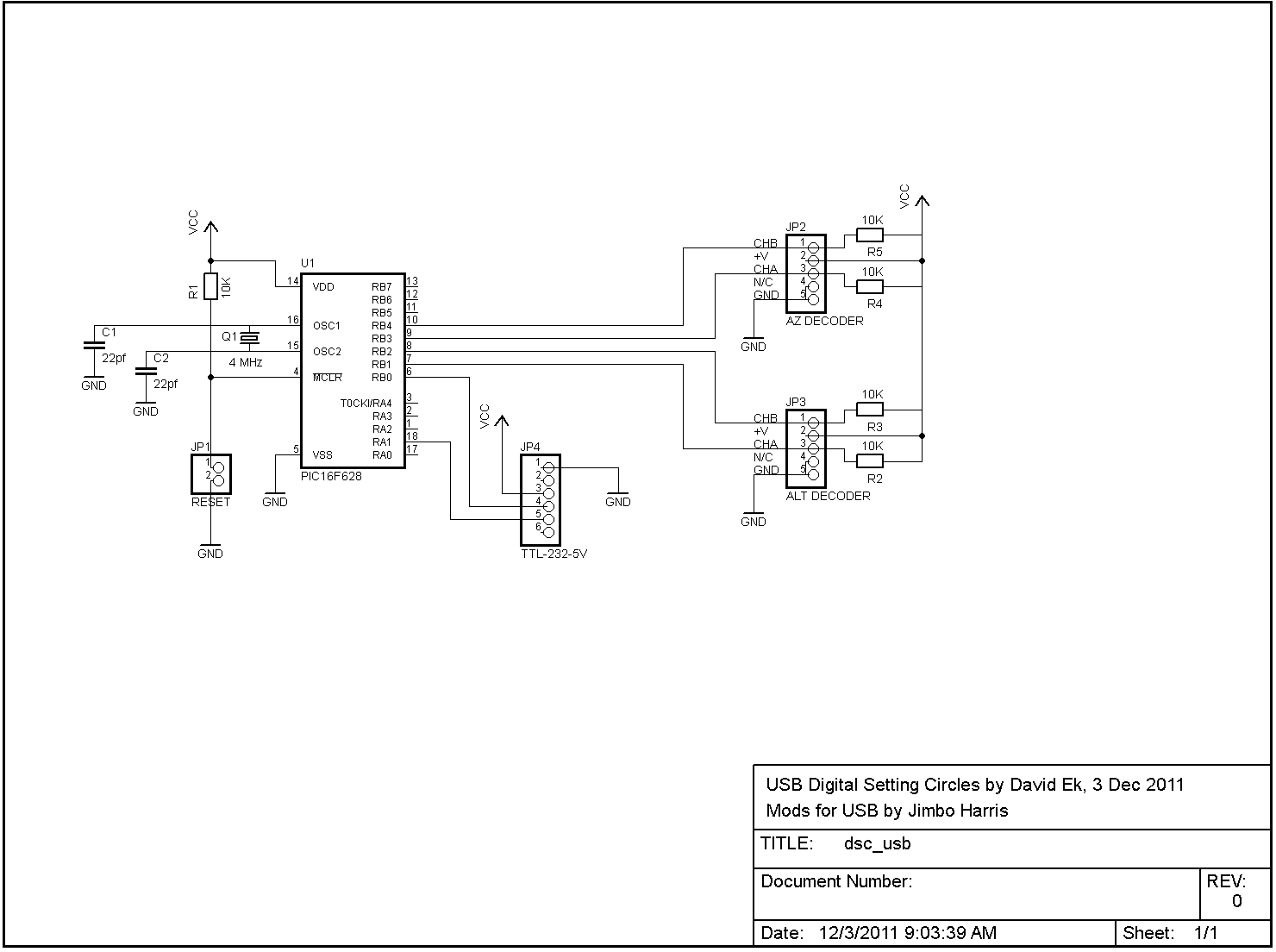
The serial version of the DSC circuit described in these pages is easily adaptable for use with a USB-serial conversion cable. FTDI manufactures the TTL-232R-5V cable, which converts TTL-level serial data directly from the PIC to USB for connection...
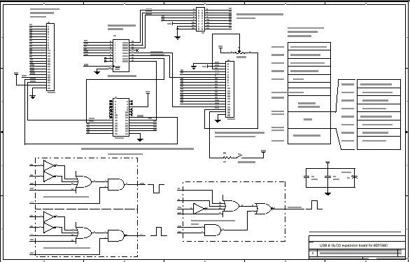
8051SBC USB and GLCD Expansion Board, electronic circuit schematic wiring diagram for the 8051SBC USB and GLCD Expansion Board. The 8051SBC USB and GLCD Expansion Board is designed to enhance the functionality of the 8051 microcontroller system by providing additional...
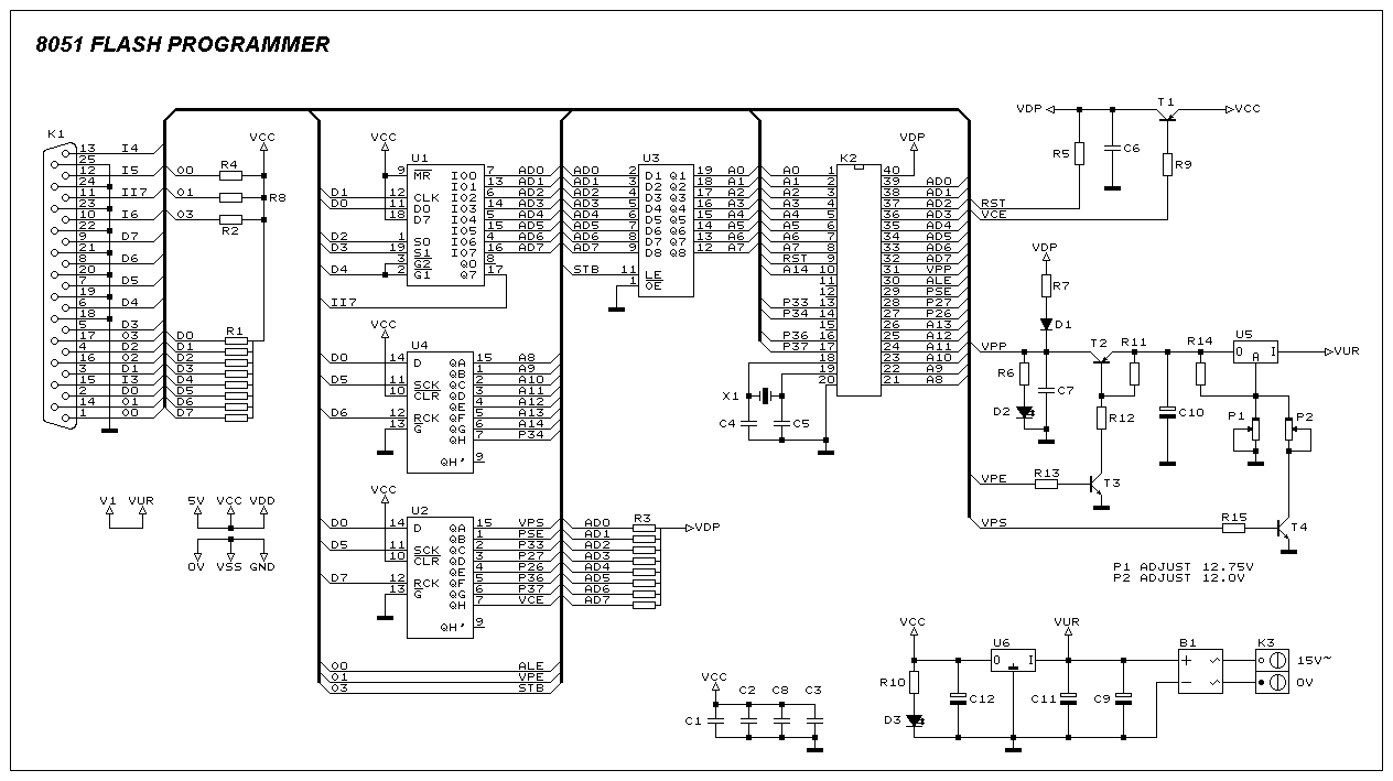
This programmer was designed in view of to be flexible, economical and easy to built, the programmer hardware utilizes the standard TTL series parts and no special components are used. The programmer is interfaced with the PC parallel port...
This project demonstrates a computer control interface using a USB board (USB Interface Project). This tutorial provides a straightforward method to control devices such as LEDs, motors, and other components via a computer using a USB board. Traditionally, devices...
The digital input board features eight distinct digital inputs available on connector JP1. Each input is equipped with separate pull-down resistors (RN1, with a recommended value of 1 MΩ) and a Schmitt-trigger. To prevent damage from improper input voltages,...
AVRDude is a program designed for burning hex code into microcontrollers. USBasp is a USB-based programmer for AVR microcontrollers. This tutorial will demonstrate how to use AVRdude to burn hex files into an AVR microcontroller using USBasp. The AVRdude...