
UPS_design_2 16f84 based UPS circuit

A full sine wave Uninterruptible Power Supply (UPS) is designed to provide a stable and continuous power output that closely resembles the characteristics of a standard AC sine wave. This type of UPS is essential for sensitive electronic equipment that requires a pure sine wave for optimal performance, such as audio/video equipment, medical devices, and computer systems.
The UPS operates by converting stored DC power from batteries into AC power through an inverter circuit. The inverter is typically controlled by a microcontroller that executes a C language source code program. This program is responsible for managing the battery charging process, monitoring the input and output voltages, and ensuring that the output waveform is a pure sine wave.
The C language source code for a full sine wave UPS includes functions for generating the sine wave signal, controlling the inverter switches (such as MOSFETs or IGBTs), and implementing protection features like over-voltage, under-voltage, and thermal shutdown. The sine wave generation is often achieved using a lookup table or a Direct Digital Synthesis (DDS) technique, which allows for precise control of the waveform frequency and amplitude.
In addition to the sine wave generation, the code handles real-time monitoring of battery status and load conditions. It may also include user interface elements for displaying operational parameters such as battery voltage, load current, and output frequency.
Overall, a full sine wave UPS system is critical for ensuring that sensitive electronic devices operate reliably during power interruptions, and the integration of C programming allows for sophisticated control and monitoring capabilities.full sine wave ups information, in English, with a detailed C language source code, English may be the weak to be careful of, a little 🔗 External reference
Related Circuits
A device designed to locate a mobile phone by emitting intermittent flashes and beeps, indicating the presence of an active mobile phone. This circuit activates even when the mobile phone is in silent mode, making it effective for detecting...
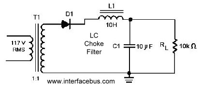
A circuit that utilizes one cycle of alternating current (AC) to produce direct current (DC). A half-wave rectifier circuit generates DC from either the positive or negative cycle of the AC input, but not both. It is important to...
A milliamp meter can function as a voltmeter by incorporating a series resistance. The required resistance is calculated by dividing the full-scale voltage reading by the full-scale current of the meter movement. For instance, using a 1 milliamp meter...
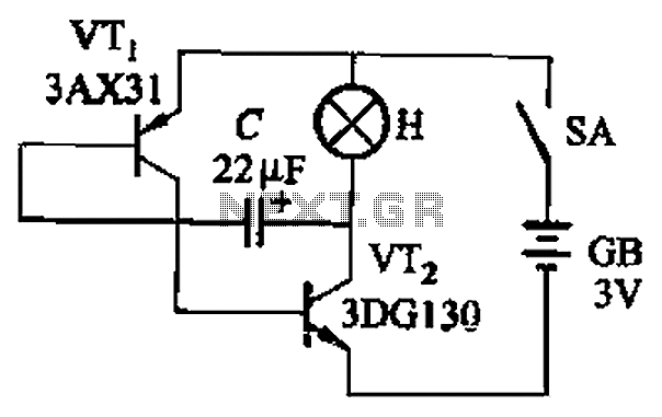
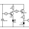
The circuit depicted in Figure 13-4 utilizes triode control. Two transistors, VTi and VTz, are coupled via a capacitor (C) to alternately turn on and off, producing a flashing light effect. The flash frequency is influenced by the capacitance...
The transmitter features a VXO circuit that drives a keyed amplifier. This keyed amplifier powers an MRF 476 final amplifier, producing approximately 2 watts of output. Additionally, a solid-state T-R switch is incorporated for the receiver. The component values...

The 1-megohm resistor protects the FET from potential damage caused by accidental sparks to its gate lead. The circuit functions adequately without this resistor; however, it is advised not to intentionally apply a charge to the gate wire using...