
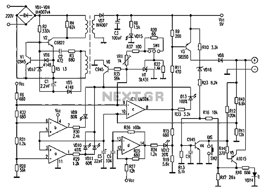
UPS Schematic

The schematic circuit diagram for a 3000 Watts Uninterruptible Power Supply (UPS) is designed to provide reliable backup power in the event of an electrical outage. This UPS is capable of handling loads up to 3000 Watts and can be adapted to support a 1000 VA load with minor modifications to the circuit components.
The primary components of the UPS include an inverter, battery bank, charger, and control circuitry. The inverter converts the DC voltage from the battery bank into AC voltage suitable for powering standard household or industrial appliances. The battery bank typically consists of lead-acid or lithium-ion batteries, which store energy for use during power interruptions.
The charger is responsible for maintaining the battery bank's charge level when mains power is available. It ensures that the batteries are charged efficiently and safely. The control circuitry monitors the input voltage, output voltage, and battery status, allowing for seamless switching between mains power and battery power.
In the event of a power failure, the control circuitry detects the loss of input voltage and activates the inverter, supplying power from the battery bank to the connected load. The UPS may also include additional features such as overload protection, short-circuit protection, and surge protection to safeguard both the UPS and the connected devices.
For the adaptation to a 1000 VA system, modifications may include adjusting the transformer rating, changing the battery capacity, or altering the inverter circuit to accommodate the lower power requirements. This flexibility allows users to customize the UPS to meet their specific needs while maintaining a high level of performance and reliability.
Overall, the UPS schematic circuit diagram serves as a crucial blueprint for constructing a robust power backup solution, ensuring continuous operation of essential equipment during power outages.UPS Schematic Circuit Diagram for 3000 Watts UPS It can also work for 1000 VA with minor modifications. 🔗 External reference
Related Circuits
Chaolitong Phone Travel Charger for Motorola models 308, 328, 338, and 368 series mobile phone batteries. This charger features a switch for nickel-cadmium, nickel-hydrogen, and lithium-ion batteries, along with a discharge function. It operates with an AC mains input...
The amplifier circuit utilizing the STK4050 integrated circuit (IC) is known for its robustness and high quality. This article presents a 200-watt power amplifier circuit based on the STK4050. The circuit features an advanced auto wiring diagram with color-coded...
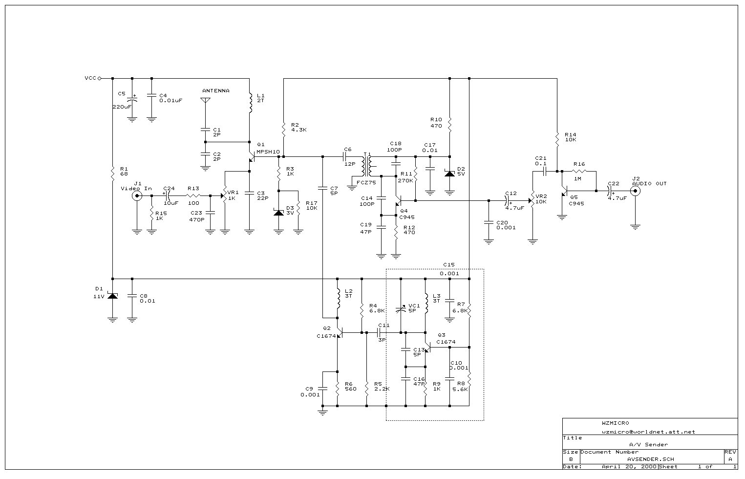
Wireless audio and visual transmission to a TV. The TV functions as a receiver, eliminating the need for a separate monitor. It can also be connected to a VCR or CCD camera, enabling the setup of a remote CCTV...
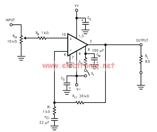
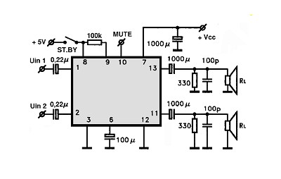
The LM3886 amplifier electronic circuit project is designed to deliver 68W of continuous average power into a 4-ohm load and 38W into an 8-ohm load with a total harmonic distortion plus noise (THD+N) of 0.1% across the frequency range...
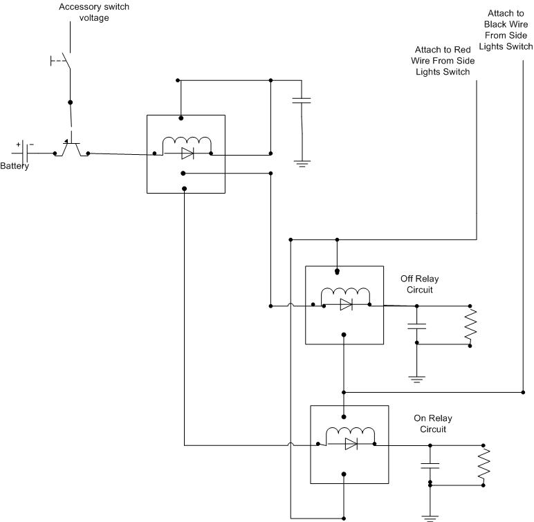
A decision has been made to install daytime driving lights for an Elise vehicle. The intention is to eliminate the need for manually pressing the button on and off repeatedly. The installation of daytime driving lights (DRLs) enhances vehicle visibility...
These accessories are low-cost, high-speed, bifet-input operational amplifiers utilizing internally compensated voltage (BI-FET II technology). They require low supply voltages while offering a wide gain bandwidth product and fast slew rate. Additionally, well-matched high voltage JFET input devices accommodate...