
Schematic Diagram UHF Wireless Video Audio Sender circuit andexplanation
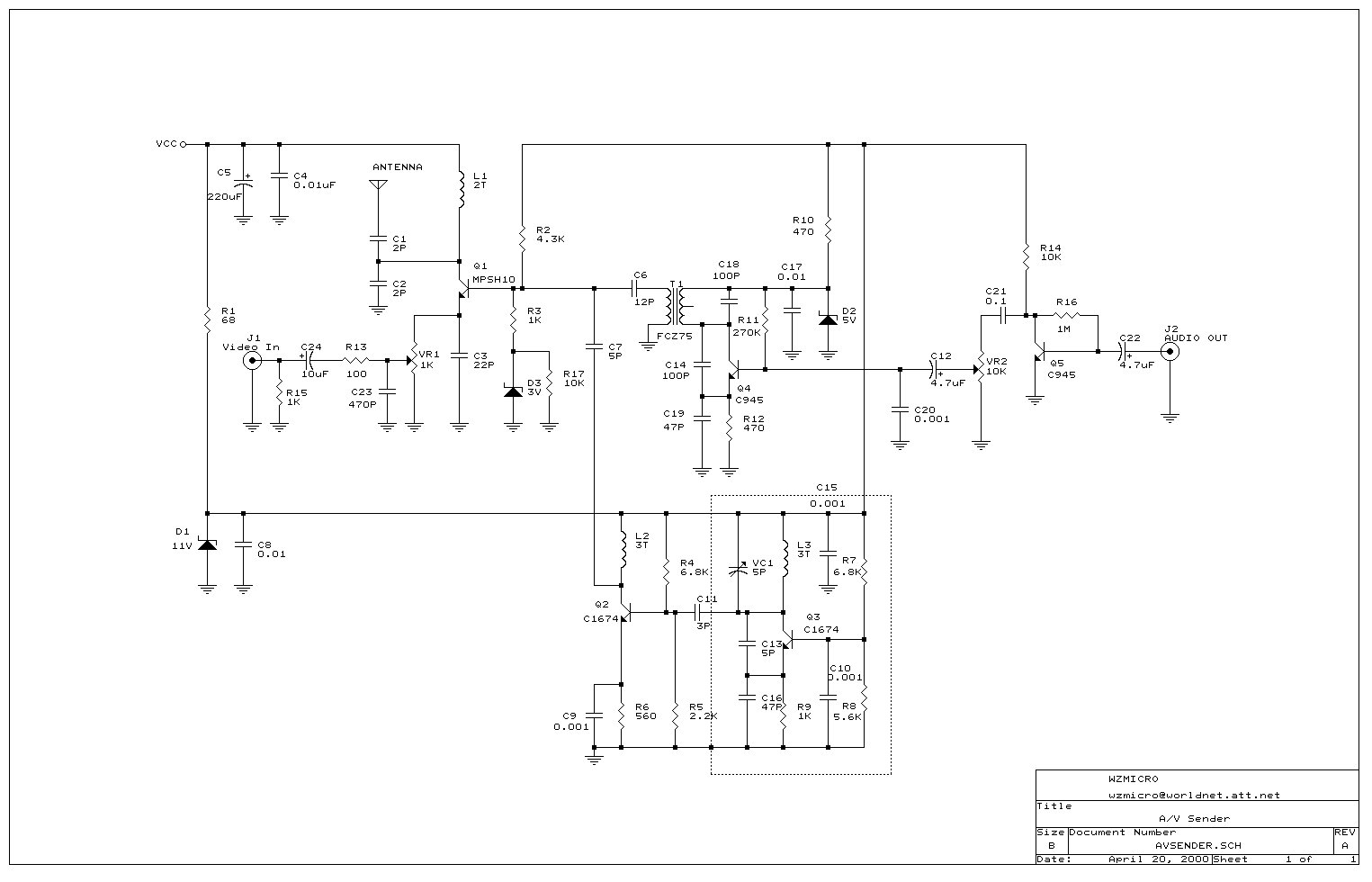
The described wireless audio and visual transmission system utilizes a Colpitts oscillator configuration, which is critical for generating the required RF signals for transmission. The oscillator circuit's design allows for a frequency range of 220 MHz to 250 MHz, making it suitable for UHF band applications. The tuning components VC1 and L3 are essential for adjusting the output frequency, allowing users to optimize the transmission for various receiving devices, such as TVs, VCRs, or CCD cameras.
The modulation of the signal is achieved through C13, which acts as a tuning capacitor that influences the rate of signal modulation. The relationship between capacitance and modulation is crucial for ensuring the clarity and quality of the transmitted audio and visual signals. R9 and C16 serve to bias the local oscillation, ensuring stable operation of the oscillator circuit. The adjustment of R9 to a lower resistance value enhances the output level of the oscillator, providing a stronger signal for transmission.
The frequency doubler configuration, consisting of Q2 and L2, allows for the doubling of the oscillator frequency, facilitating the generation of higher frequency signals necessary for effective transmission. The mixer stage, formed by C7, FCZ7S3R5, Q4, C14, C19, and R12, is responsible for combining the audio and visual signals into a single RF output. This integration is critical for ensuring that both types of signals are transmitted simultaneously, maintaining synchronization between audio and video.
The RF amplifier Q1 boosts the combined signal before it is transmitted via the antenna, ensuring adequate signal strength for reception. The tuning process, facilitated by the trimmer on VC1, requires careful adjustment to align with the selected television channel, which is essential for optimal reception. A spectrum analyzer can significantly aid in this process by visually displaying the frequency spectrum, allowing for precise tuning adjustments.
The use of an IF transformer in the circuit is vital for synchronizing audio and video signals, ensuring that they are transmitted at compatible frequency levels. This synchronization is crucial for maintaining the integrity of the transmitted signals, as any discrepancies can lead to issues such as image blurriness or audio-video desynchronization. Adjusting the IFT can help resolve these issues, allowing for fine-tuning of the output for improved image clarity on the receiving television.wireless audio and visual transmission to a TV. The TV acts as a receiver, eliminating the need to buy a separate monitor. You can also hook it up to a VCR or CCD Camera, and even set up a remote CCTV security system Q3, VC1, C13, C16 and L3 all make up a colpitts oscillator circuit that fluctuates form 220~250 MHz. You can regulate the frequency to any value within this threshold by tuning VC1 or L3. C13 modulates the signal rate. When the capacitance increases, so does the modulation. R9 and C16 bias the local oscillation. If you lower R9 ²s frequency to 680W the oscillator`s output level will increase. Q2 and L2 act as a frequency doubler. C7, along with FCZ7S3R5 (IF transformer), the Q4 transistor, C14, C19 and R12 all make up the mixer. This mixer takes both audio and visual signals together and mix them into one and passes through RF Amplifier Q1 to transmit the signal to the antenna. Turning the blue component`s trimmer on VC1 varies the frequency. When we turn the trimmer, the television`s channel has to be changed accordingly. It is easier to tune the A/V Sender if you have a spectrum analyzer to help you find the correct frequencies.
If the frequency is tuned to 474 MHz then this would be the equivalent of your TV`s channel 14 UHF band. The IF transformer is used to synchronize the audio and video frequencys level radio. If the TV`s image is too blurry then you can adjust the IFT to fine-tune the image. 🔗 External reference
Related Circuits
This circuit is designed to detect incoming calls on a cellular phone, even when the phone's ringer is turned off, by utilizing a flashing LED. The device should be positioned a few centimeters away from the cellular phone, allowing...
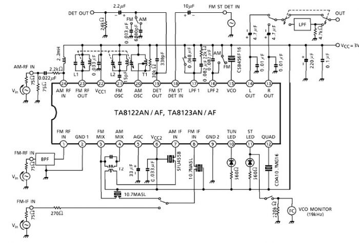
A simple low-power AM/FM radio receiver electronic project can be designed using the TA8122 integrated AM/FM receiver, manufactured by Toshiba Semiconductor. This radio receiver circuit is suitable for portable radio applications or other similar devices. The TA8122 radio receiver...
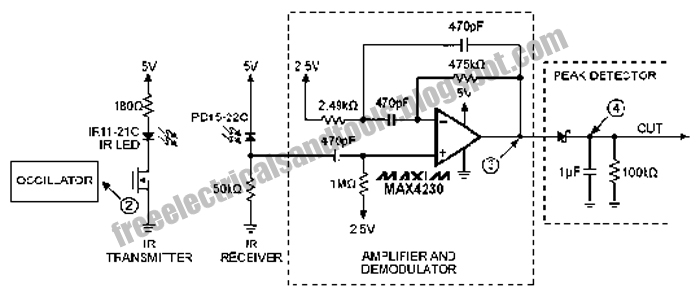
The following circuit illustrates an Infrared Proximity Sensor Circuit Diagram. This circuit is based on the MAX4230 integrated circuit. Features include a 10 kHz oscillator. The Infrared Proximity Sensor Circuit utilizing the MAX4230 integrated circuit is designed to detect the...
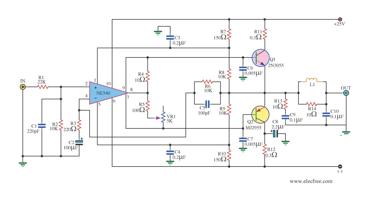
When the power supply reaches the circuit and the input signal is applied, the sound signal is processed through capacitor C1 and resistor R1 for signal coupling and noise reduction. The modified signal then reaches pin 3 (non-inverting) of...
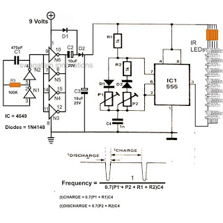
The 4049 section serves as a fundamental voltage doubler circuit, enhancing a 9 V supply to approximately 15 V. This elevated voltage subsequently acts as the supply voltage for the following 555 pulse modulator section. A key characteristic of...
The circuit described is a simple intercom system that utilizes a single LM386 integrated circuit, a 2N3904 transistor, and several additional components. The LM386 is a widely recognized amplifier IC commonly employed by electronics enthusiasts in audio applications. In...