
USB DC Power Supply from Cigar Lighter Socket

The circuit design consists of several key components to ensure efficient voltage conversion and regulation. At the core of the circuit is a buck converter, which steps down the 12V input to the desired 5V output. The buck converter typically includes an inductor, a diode, and a switch (usually a transistor) that work together to regulate the output voltage.
The input voltage is first filtered through a capacitor to remove any high-frequency noise, ensuring a clean input signal for the buck converter. The inductor stores energy when the switch is closed and releases it when the switch is open, allowing for a smooth transition and stable output voltage. The output is further stabilized by a capacitor that reduces voltage ripple, providing a consistent power supply for connected devices.
To protect the circuit from overcurrent conditions, a fuse or resettable polyfuse can be integrated into the design. This component disconnects the load in the event of excessive current flow, safeguarding both the circuit and the connected devices.
Additionally, the circuit may include a USB connector for easy interfacing with various devices. This connector typically consists of four pins: VBUS (5V), D- (data minus), D+ (data plus), and GND (ground). Proper pin configuration and connection are essential for ensuring compatibility with USB standards.
Overall, this USB power socket circuit is designed to provide a reliable and efficient power source for USB-powered devices, making it a valuable addition to applications requiring portable power solutions.The diagram shows the circuit of a versatile USB power socket that safely converts the 12V battery voltage into stable 5V. This circuit makes it possible t.. 🔗 External reference
Related Circuits
A 2004 Chevy Tahoe lost power while driving at 60 mph, causing the tachometer to drop to zero. The vehicle has been in the shop for three days, and the mechanics are struggling to identify the issue. They have...

UPDATED 2014 This project presents the original high-power mobile phone jammer circuit, with all updates posted here. Caution is advised regarding the use of this device, as it is illegal. The purpose of sharing this circuit is solely for...
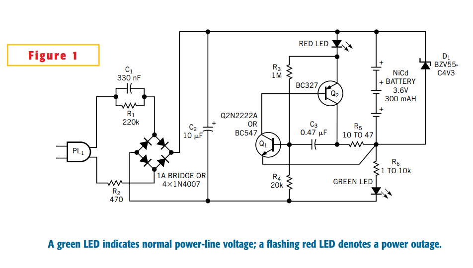
This Design Idea expands on a circuit in a previous one to configure a power-outage detector with a flashing alarm (Figure 1, Reference 1). The circuit plugs into a mains outlet and uses trickle-charged nickel-cadmium batteries. The green-LED monitors...
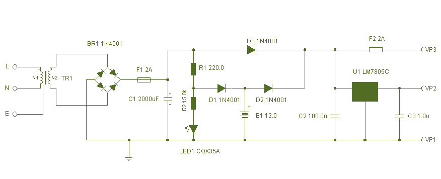
This circuit is a simple form of the commercial UPS, the circuit provides a constant regulated 5 Volt output and an unregulated 12 Volt supply. In the event of electrical supply line failure the battery takes over, with no...
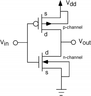
The fundamental issue presented is the perception that logic gates in a circuit seem to generate power from nothing, which contradicts the principles of physics. For instance, consider two NOT gates connected in series. It appears that the first...
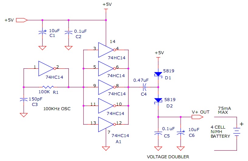
The circuit described will trickle charge a four-cell pack of AA or AAA NiMH batteries. It draws current from the +5V available from a USB connection and supplies approximately 70mA of current to the battery. This current level is...