
UPS Power Supply

The circuit operates as a basic Uninterruptible Power Supply (UPS) designed to provide both regulated and unregulated voltage outputs. The main components include a transformer (TR1), a rectifier, a voltage regulator, and a battery backup system.
TR1 is a step-down transformer with a primary winding designed for the local electrical supply voltage, specifically rated for 240 Volts in the UK. Its secondary winding is configured to output a minimum of 12 Volts at 2 Amps, although it can be designed for higher voltages, such as 15 Volts, depending on the application requirements. The transformer’s output is connected to a rectifier circuit, which converts the AC voltage to a DC voltage suitable for battery charging and powering the load.
The circuit features a battery backup system that engages automatically during power outages. The battery, which can be selected based on the desired output voltage, ensures continuous power supply without interruption. The regulated output is achieved using a linear voltage regulator, such as the 7805 for 5 Volts or the 7815 for 15 Volts, which maintains a stable output voltage even in the event of fluctuations in the input voltage.
In terms of safety, a slow-blow fuse (FS1) is included to protect against short circuits and overcurrent situations. This fuse allows for temporary surges in current, which may occur during normal operation, but will blow if a sustained overcurrent condition arises, thereby protecting the circuit components.
The flexibility of this UPS circuit allows for customization according to the specific voltage requirements of different applications. By selecting appropriate regulators and battery configurations, users can easily adapt the circuit to meet various power supply needs. The design also emphasizes reliability, ensuring that the regulated supply remains free from voltage spikes during switchover from mains power to battery power.This circuit is a simple form of the commercial UPS, the circuit provides a constant regulated 5 Volt output and an unregulated 12 Volt supply. In the event of electrical supply line failure the battery takes over, with no spikes on the regulated supply.
This circuit can be adapted for other regulated and unregulated voltages by using different regulators and batteries. For a 15 Volt regulated supply use two 12 Volt batteries in series and a 7815 regulator. There is a lot of flexibility in this circuit. TR1 has a primary matched to the local electrical supply which is 240 Volts in the UK. The secondary winding should be rated at least 12 Volts at 2 amp, but can be higher, for example 15 Volts. FS1 is a slow blow type and protects against short circuits o 🔗 External reference
Related Circuits
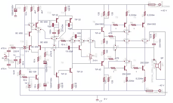
This post presents the circuit schematic diagram for a 500-watt mono power amplifier. As of July 18, 2012, the intention is to create a power sound system with a total output of 1000 watts in stereo. The design utilizes...
This document contains a collection of schematic diagrams, datasheets, images, and tips for switch mode power supplies (SMPS) utilizing the TL494, LM339, KA7500, and IC2003 integrated circuits. Switch Mode Power Supplies (SMPS) are crucial components in modern electronic devices, providing...
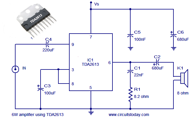
A simple and easy-to-build Hi-Fi audio power amplifier circuit is presented here. This 6-watt Hi-Fi audio amplifier circuit utilizes the TDA2613 integrated circuit (IC). The circuit design employs the TDA2613, which is a high-performance audio amplifier IC known for its efficiency...
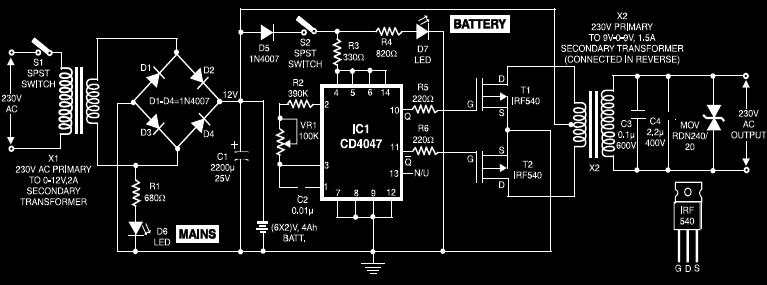
This circuit diagram of a UPS is designed for use with cordless telephones that cannot operate during a power failure. Since the UPS is intended solely for telephones, its output power is limited to 1.5W. This UPS circuit is...
A regulated voltage that can be adjusted to suit various applications is desired. This Adjustable Power Supply is compact, simple to construct, and can be modified to produce different output voltages. The Adjustable Power Supply circuit typically utilizes a linear...
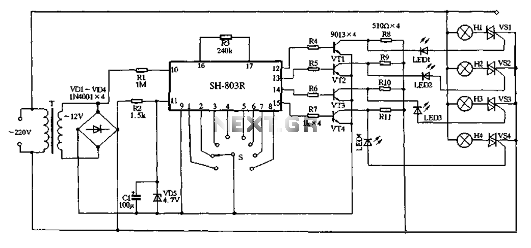
22V AC is supplied through thyristors VSl to VS4 for lighting control. The current is routed through transformer T, followed by rectification using diodes VD1 to VD4, and regulated by VD5 to provide a filtered output of approximately 4.7V...