
USB Joystick

The joystick controller design leverages the capabilities of the PIC18F2455 microcontroller, which features sufficient input/output ports to manage the required axes and buttons. This microcontroller is well-suited for handling multiple analog inputs from potentiometers and digital inputs from push buttons. The USB interface allows for direct connection to a PC, facilitating easy integration without the need for additional drivers, as it adheres to the USB Human Interface Device (HID) class specifications.
The circuit should incorporate a robust power management system to ensure stable operation during extended use. The choice of capacitors is critical; C1 and C5 should be selected to handle the expected load and provide adequate filtering to prevent voltage fluctuations that could affect performance. C2's role in stabilizing the USB voltage is vital for maintaining the integrity of the microcontroller's operation.
For the potentiometer connections, each of the five axes can be controlled by a linear potentiometer, which translates the physical movement into an electrical signal that the microcontroller can interpret. The non-critical nature of the resistivity value allows for flexibility in component selection, enabling hobbyists to source readily available potentiometers. The wiper connection to pin 3 of the connector is essential, as it provides the variable voltage input to the microcontroller corresponding to the position of the joystick.
In summary, this joystick controller project presents a comprehensive solution for enthusiasts looking to enhance their flight simulation experience. By utilizing the PIC18F2455 microcontroller and a well-thought-out circuit design, users can create a highly functional and customizable joystick controller that seamlessly integrates with modern PC systems.It makes sense to build your own individual joystick. Especially the flight simulation enthusiasts like to build cockpit parts with the look and feel of original aircraft parts. Such self made hardware needs an joystick controller that meets the requirements of the hobbyists. This project is ideal to build up devices with up to 5 axi s and 24 buttons. It is based on the microcontroller PIC18F2455. I was inspired by a project on opencockpits. com. There is used the outdated PIC16C745 to design a similar project. The operating system of any modern PC recognizes the device as a joystick with 3 additional axis (sums up to 5 axis) and 24 buttons, not needing additional software or driver. The joystick-controller is powered and controlled via USB. The capacitors C1 and C5 stabilize the supply voltage. C2 is stabilizing the USB-voltage if the internal 3. 3V-voltage regulator. To every 3-pin-connector SV1 bis SV5 can be hooked up a linear 10-kOhm-potentiometer (the resistivity value is non critical).
The sliding contact of the potentiometer has to be connected to pin 3 of the connector. 🔗 External reference
Related Circuits
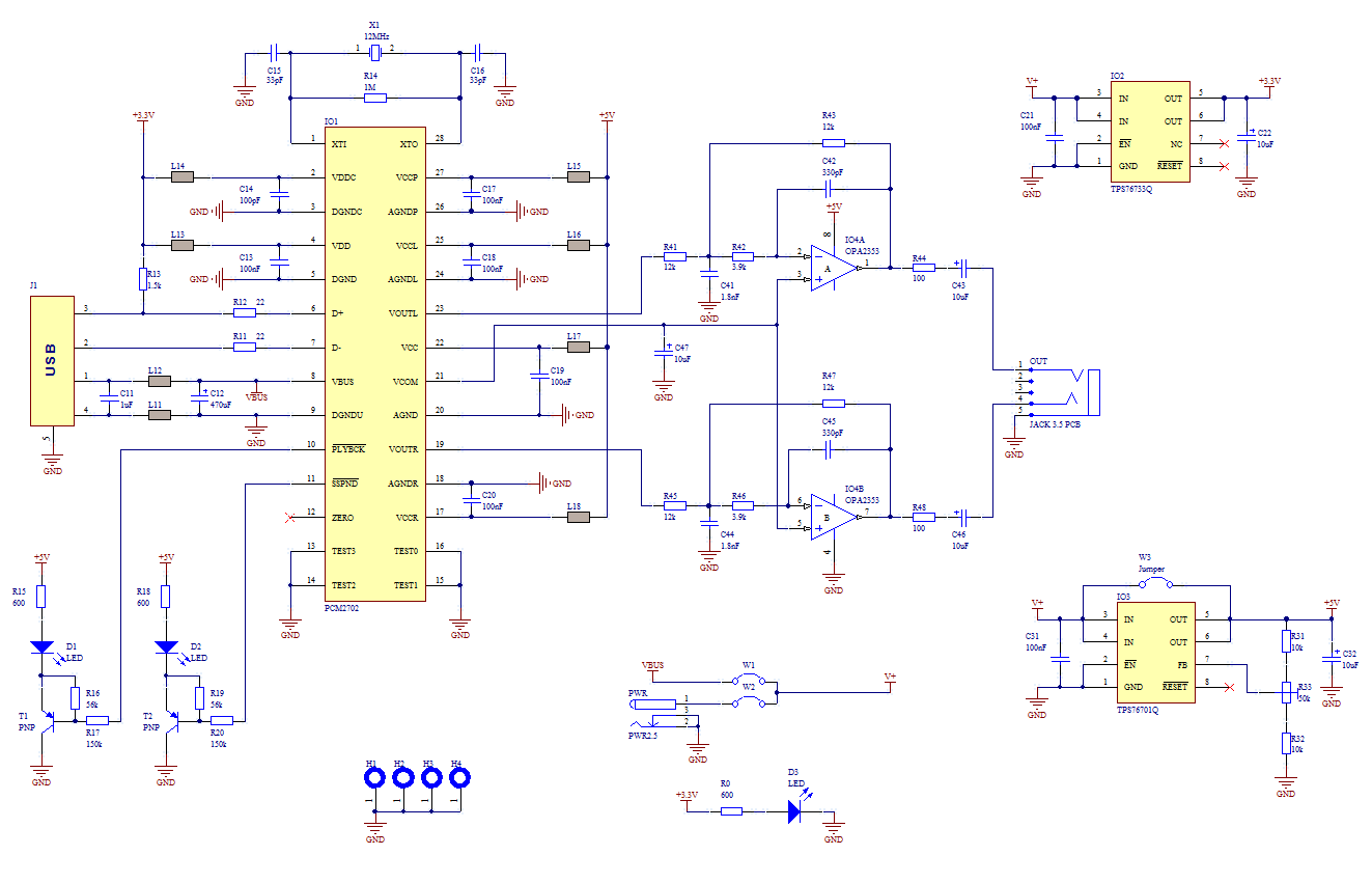
The core of this construction is 16-Bit Stereo Digital-To-Analog Converter with USB interface PCM2702. PCM2702 needs only a few additional parts to work. The schematic is not complex. The sound card can be powered directly from the USB port...
Model aircraft pilots utilize PC flight simulator software to practice handling model aircraft without risking damage to real models. It is advantageous to use the actual model aircraft remote control (RC) as the input device for the software, necessitating...
The simplest solution for implementing joystick control for a robot is to program the actions in software on a microcontroller. However, many users prefer off-the-shelf components, thus this circuit is designed using diodes, resistors, transistors, and a FAN8200 motor...
After completing several V-USB tutorials, the next project undertaken was to create a compact USB HID keyboard device that types a password stored in EEPROM each time it is connected. The password can be regenerated by pressing the CAPS...
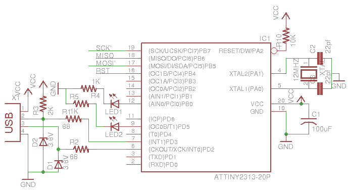
This is a low-cost AVR programmer using the ATtiny2313. The schematic diagram is provided below. First, set up the circuit as shown. One important consideration is to configure the fuse bits using the command: avrdude -c usbasp -p t2313...
USB Battery Charger for Lithium Ion batteries using the LM3622 is a specialized charger circuit designed to operate with power sourced from a USB connection. The current consumption of the LM3622 is limited to 400mA by a resistor (R1),...