
DIY USB password generator

The USB HID keyboard device is designed to provide a secure and user-friendly method for managing passwords. It utilizes the ATtiny85 microcontroller, which is programmed to act as a Human Interface Device (HID) compliant keyboard. This allows the device to interface seamlessly with computers, enabling it to send keystrokes as if it were a standard keyboard.
The password regeneration feature is initiated through a simple user interaction with the CAPS LOCK key. The EEPROM is used to store the password securely, and the regeneration process is designed to ensure that users can easily create new passwords without the need for complex programming or technical knowledge.
In terms of hardware design, the device is compact, making it suitable for integration into various enclosures. The choice to simplify the original design by omitting non-essential components enhances reliability and reduces the overall size, which is particularly beneficial for portable applications.
The inclusion of a boot-compliant HID descriptor ensures that the device can communicate effectively with a wide range of operating systems without requiring additional drivers. This feature is crucial for maximizing compatibility and ease of use across different platforms.
The firmware is structured to handle input and output efficiently. The buildReport() function is integral to the operation, as it translates characters from a message buffer into the corresponding USB key codes. This real-time translation enables the device to function smoothly, providing users with an immediate response when generating passwords.
The generate_character() function is another key component, responsible for producing random characters from a predefined set. This randomness is crucial for enhancing security, as it minimizes the predictability of generated passwords.
Overall, the design and implementation of this USB HID keyboard device exemplify a practical approach to password management, combining ease of use with effective security measures. The project not only demonstrates the capabilities of the ATtiny85 microcontroller but also illustrates the potential for innovative solutions in personal computing security.Having done half a dozen V-USB tutorials I decided it`s time to whip up something cool. As USB keyboards were an area untouched, I decided to make a small USB HID keyboard device that types a password stored in EEPROM every time it`s attached. A new password can be generated just by tabbing CAPS LOCK a few times (4 times to start password regenera
tion and one tab for each password character generated, 10 is the default password length). Below you can see the device in action: The place I work at requires me to change my password every few months so this would be one way to skip remembering a new password altogether (as long as I remember to write it down before regenerating a new one so password can be changed :). The device is powered with a simplified version of the hardware I used in my ATtiny85 USB tutorial I stripped away the LCD, reset pullup and both capacitors.
If you`re better in cramming components inside enclosures I suggest adding at least a 0. 1 uF capacitor between VCC and GND, but it seems to work fine even without it: The enclosure was graciously donated by an old 512 MB flash drive. I couldn`t make myself to break the USB connector from the circuit board inside, so I stripped appart a short USB cable instead (shown on left): I soldered the connector first, then the zener diodes, then resistors and jumpers, and finally VCC, GND and the ATtiny itself.
I used the following tricks to make all ends meet: I was pretty satisfied the result and the fact that it actually worked! The board did not initially fit into the very snug space in the plastic enclosure, so I had to use a Dremel to trim its insides a bit, but after that, everything snapped right back (click for larger versions): Update: For those who are building this project I recommend you first build it on a breadboard, and only when you have it working, solder it to a veroboard.
Here are two additional, extra-large pictures of the configuration I used to help you in the component layout: The device presents itself to the computer as a USB HID keyboard. To enable communication to the device, it is a boot-compliant keyboard that can receive LED status changes from the computer.
HID descriptor is from Frank Zhao`s USB business card example and I also looked at Frank`s code to understand how LED state is sent to the device (in short, PC sends a control message with 1 byte of data, the LED state bit mask). The code is mostly based on my USB HID mouse example except for the usbsconfig. h and HID descriptor changes required to implement a boot keyboard. I`ve documented the code but here are some highlights if you want to understand it better: buildReport() is called by the program main loop to send keypresses to PC one by one it translates characters in messageBuffer to USB key codes on the fly generate_character() is used to return random keypresses it is currently written to return alphanumerics, hyphen and underscore (64 symbols make it simple to select one so each has equal chance of being selected without additional logic) I`ve packed the source files with the schematic, critical pictures and a Makefile.
In addition to make flash you of course need to update the fuse bits to use the PLL clock source see details from my previous tutorial for that. I also very strongly recommend testing the device using a breadboard before soldering it, because otherwise reflashing will be a major pain.
And of course, if you build it, try it at your own risk and remember that once you reprogram the password, nothing will be able to restore it. I recommend storing passwords generated with the device to a safe place just to be sure. I found out yesterday that SparkFun is carrying an almost identical piece of hardware, the AVR Stick.
So if you order one and reprogram it with this firmware (pin configuration in usbconfig. h needs to be updated in that case), you can avoid some soldering (although not all, you`ll likely need to solder in the programming header). I asked SparkFun if they`d be interested to make a 2. 0 ³ model of their AVR Stick with actual USB connector and enclosure to go with the package, and my password generation firmware preloaded.
If you think that`s a good idea, now would be a great time to send them feedback. I`d also be interested in covering additional hacks and tutorials with such a device. :) Alvin Chang is currently (December 1st 2012) running a Indiegogo project to build a device very similar (and inspired by) my DIY version. In case you`re interested in getting a ready-made version, be sure to check Mr. Chang`s project out: Aladdin: The Key to Your Computer. 🔗 External reference
Related Circuits
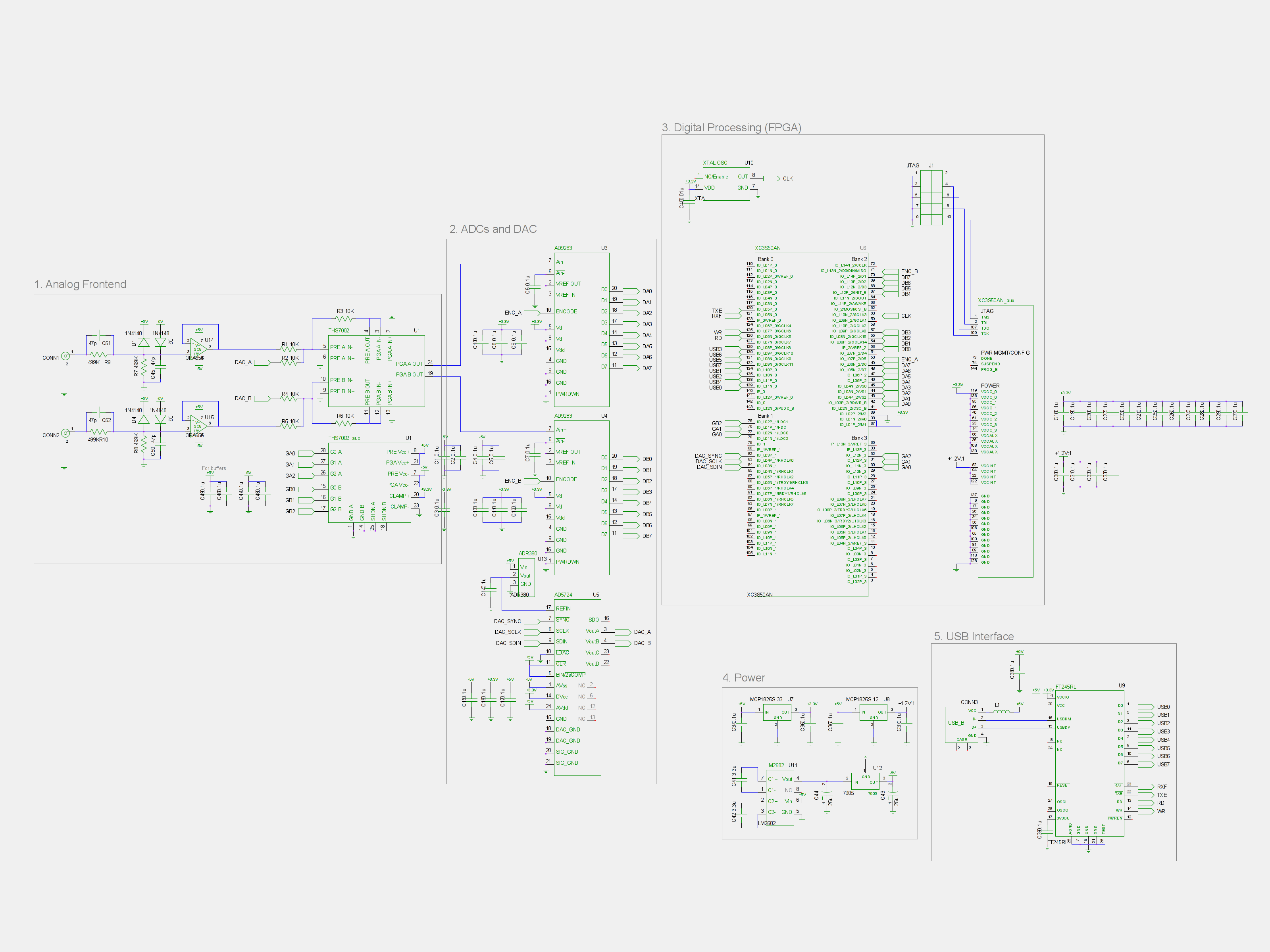
There are plans to achieve a sampling rate of 1 Gsps in the future using interleaved ADCs and staggered clocking; however, the initial iteration will only support 100 Msps, which is the maximum from a single ADC. The most...
The circuit is straightforward, utilizing a single IC chip, the ICL8038 function generator chip, which produces simultaneous sine, square, and sawtooth waveforms. The circuit consists of a minimal number of components, including two resistors, one transistor, five trimpots, and...
A high-quality tone burst generator can be constructed using a 556 Dual Timer. The first half of the timer can be configured as a one-shot, while the second half can function as an oscillator. The 556 Dual Timer is an...
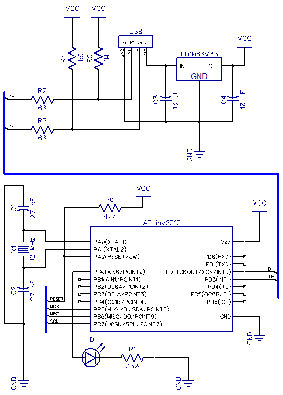
This is the second part of a USB tutorial for the ATtiny2313 microcontroller and the V-USB library. The first part covered how to derive 3.3V from USB to power circuits. In this section, the setup will be expanded with...
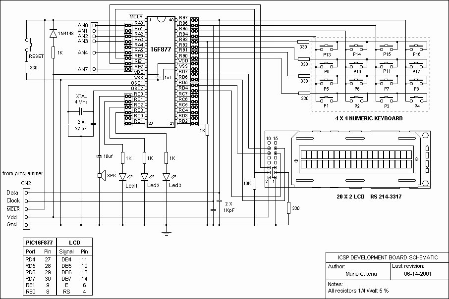
A schematic of a board featuring the PIC16F84 microcontroller, along with other compatible PIC microcontrollers that can be connected to the USB PICKit2 programmer. Additionally, there are concerns regarding the potential damage to the programmer when experimenting with oscillator...
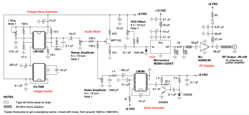
A DIY GSM jammer schematic diagram designed to disrupt cellular mobile phone signals operating within the GSM1900 frequency range of 1930 MHz to 1990 MHz. The GSM1900 standard is utilized in the USA, Canada, and most countries in South...