
USB powered device with multiple Decoupling Capacitors

In designing a USB powered device with multiple ICs, careful consideration must be given to the decoupling strategy employed to ensure stable operation and minimize noise. Each IC typically requires decoupling capacitors to filter out high-frequency noise and provide a stable power supply. The use of a combination of capacitors, including small ceramic capacitors (e.g., 0.1µF) for high-frequency decoupling and larger electrolytic or tantalum capacitors (e.g., 2.2µF and 4.7µF) for bulk decoupling, is common practice.
To adhere to the USB specification, which limits the total decoupling capacitance to 10µF, it is crucial to analyze the configuration of these capacitors. When capacitors are connected in parallel, their capacitances add up, which can lead to exceeding the maximum allowed capacitance. Therefore, it may be beneficial to strategically place the smaller capacitors as close as possible to each IC to effectively decouple high-frequency noise, while positioning the larger capacitors slightly further away to provide bulk decoupling without exceeding the capacitance limit.
In scenarios where multiple ICs are present, it may be advantageous to group the larger decoupling capacitors of certain ICs together, thereby allowing for a shared bulk decoupling solution. This approach can help maintain compliance with the USB capacitance limit while still providing adequate power stability to each IC. Additionally, careful layout considerations, such as minimizing trace lengths and ensuring a solid ground plane, can further enhance the effectiveness of the decoupling strategy, leading to improved overall performance of the USB powered device.A USB powered device with multiple IC`s. From what I`ve read it`s standard practice to use a combination of multiple range capacitors for decoupling each individual IC, with the smallest being as close as possible and larger capacitors not too far away. According to this source, the maximum allowed decoupling capacitance for a USB device is 10uF. With several IC`s all having a combination of 0. 1uF and 2. 2uF/4. 7uF decoupling capacitors, I`m easily exceeding this limit because they`re all in parallel. The only solution I can think of is to reduce/eliminate the larger decoupling capacitor and/or try to clump a few IC`s larger decoupling capacitors together while keeping the smaller decoupling capacitors close to each IC. 🔗 External reference
Related Circuits
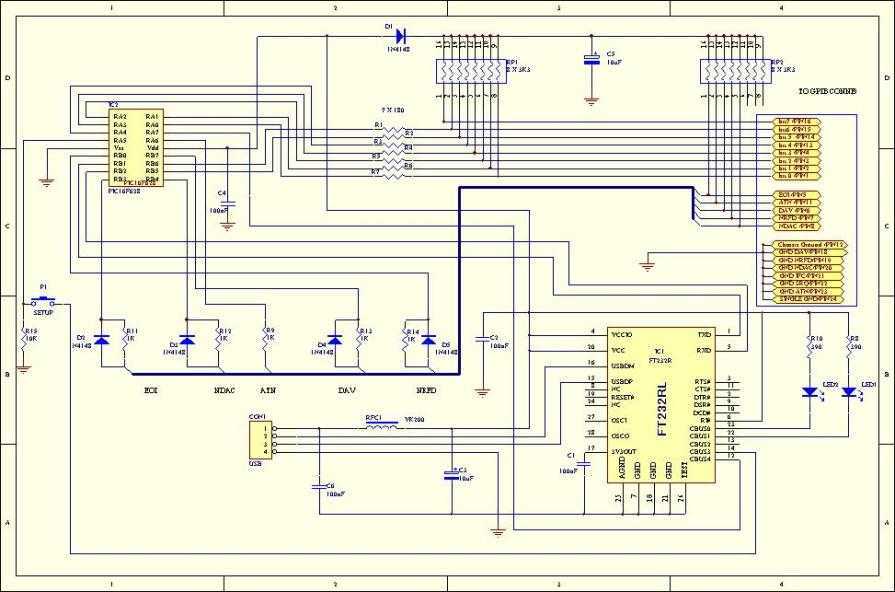
This adaptor will capture plots or prints of your GPIB instrument to your PC through the USB port. It fills the need of anybody who has a test instrument with the GPIB port and likes to get the screen...
This project is designed to charge a pair of AA Nickel Metal Hydride (NiMH) or Nickel Cadmium (NiCd) cells using a laptop's USB port for power. It addresses the need for a convenient charging solution. Any USB port can...
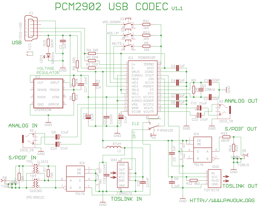
This is a USB sound card featuring the PCM2902 chip. It was designed to test the D/A converters and includes a simple circuit based on the PCM2902. The sound card is equipped with analog input and output, an electrical...
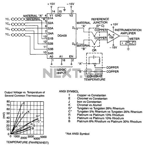
To decouple the sensors from the meter amplifier, either a reference junction at 0°C or a bucking voltage set at room temperature may be used. The latter method is simpler but is sensitive to changes in ambient temperature. The...
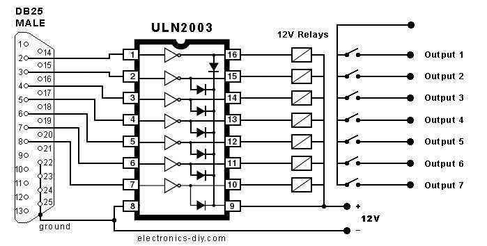
This is a very easy and fun to build project that will allow you to control up to eight external devices through your computer's parallel port. You may for instance control different appliances such as lamps, computers, printers, TV...
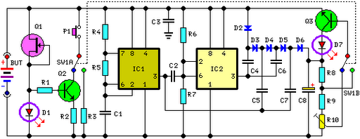
This circuit performs a rapid battery test without requiring a power supply or costly moving-coil voltmeters. It offers two testing ranges: when switch SW1 is positioned as indicated in the circuit diagram, the device can test batteries ranging from...