
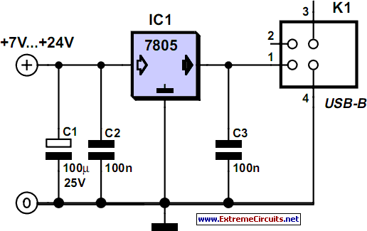
Build a USB Powered AA NiMH and NiCd Battery Charger

The design of this charger integrates several critical electronic components to ensure efficient charging and safety. The LM393 comparator serves as a temperature monitoring and control mechanism, while the thermistor provides real-time feedback on the temperature of the cells being charged. The use of a voltage divider formed by R3 and TR1 allows for precise voltage regulation based on temperature, which is essential for preventing overheating and potential damage to the cells. The charging current is carefully managed through the transistor Q1, which acts as a switch to control the flow of current based on the comparator's output. The overall design emphasizes efficiency and safety, making it suitable for charging NiMH and NiCd cells while minimizing the risk of overcharging or overheating. This project exemplifies a practical application of electronic components in creating a user-friendly and efficient battery charging solution.This project, which can charge a pair of AA Nickel Metal Hydride (NiMH) or Nickel Cadmium (NiCd) cells using a laptop`s USB port for power, arose to address part of that problem. (By the way, if you want to lighten your laptop load, take a look at the MoGo Mouse. ) Any USB port can supply 5V at up to 500mA. The USB standard specifies that a device may not use more than 100mA until it has negotiated the right to use 500mA,
but apparently no USB ports enforce that requirement. This makes the USB port a convenient source of power for devices such as this charger. The USBCell is a 1300mAh AA NiMH cell with a removable top that allows it to be plugged directly into a USB port. No separate charger is needed. Unfortunately, the cell capacity is very low (most NiMH AA cells are 2500mAh these days), and each cell requires its own port.
There is a two cell USB powered AA charger available, sold under a variety of names, but it charges at a very low 100mA rate. The distributor calls it an overnight charger , but at 100mA, a 2500mA cell would take about 40 hours to charge (40 instead of 25 due to the inefficiencies of charging at low currents).
I found a 2/4 cell charger that can be powered by a USB port, auto adapter, or wall wart, but it is as large as the wall charger I`m trying to replace. Different ones can be found here and here, but these take 10 to 12 hours to charge 2500mAh cells. [December 2007 Update: Sanyo has introduced a USB powered charger for their Eneloop batteries. This charger has none of the drawbacks listed above, and will charge a pair of 2000mAh cells in about 5 hours, or a single cell in half that time.
Although designed for Eneloops (see my review ), it will work with regular NiMH cells as well. Watch for a review on this site soon. ] The charger in this project is designed to charge two AA NiMH or NiCd cells of any capacity (as long as they are the same) at about 470mA. It will charge 700mAh NiCds in about 1. 5 hours, 1500mAh NiMHs in about 3. 5 hours, and 2500mAh NiMHs in about 5. 5 hours. The charger incorporates an automatic charge cut-off circuit based on cell temperature, and the cells can be left in the charger indefinitely after cut-off.
The heart of this charger is Z1a, one half of an LM393 dual voltage comparator. The output (pin 1) can be in one of two states, floating or low. While charging, the output is pulled low by an internal transistor, drawing about 5. 2mA of current through Q1 and R5. Q1 has a beta of about 90, so about 470mA will flow through into the two AA cells being charged. This will fully charge a pair of 2500mAh cells in just over 5 hours. TR1 is a thermistor that is in direct contact with the cells being charged. It has a resistance of 10k © at 25 °C (77 °F), which varies inversely with temperature by about 3. 7% for every 1C ° (1. 8F °). R3 and TR1 form a voltage divider whose value is applied to the inverting input (pin 2, Vtmp). At a temperature of 20 °C (68 °F), TR1 is about 12k ©, which makes Vtmp about 1. 76V. Once the cells are fully charged, the charge current will literally go to waste, in the form of heat. As the cell temperature rises, TR1 ²s resistance drops. At 33 °C (91 °F), the resistance will be about 7. 4k ©, which makes Vtmp about 1. 26V, which equals the Vref voltage. As the temperature rises above 33 °C, Vtmp will become less than Vref, and the open-collector output of Z1a will float high.
Therefore, the current flowing through R5 is greatly reduced, as it is now limited by R1, R2, and R4. As a result, the current flowing through Q1 and the cells is reduced to a 10mA trickle charge rate. Also, because R4 is now connected to +5V through R5 and Q1 instead of being held at 0. 26V by Z1a, the Vref voltage changes to about 2. 37V. This guarantees that as the cell temperature drops, the charger won`t tu 🔗 External reference
Related Circuits
This design integrates power-on and low-battery indication features, capable of operating with any battery voltage up to 15V. It exhibits a very low current drain of 2mA or less. The circuit design incorporates a power-on indicator that activates when the...
A simple battery charger is designed to disconnect the battery when the charge voltage reaches its nominal level and reconnect when the battery voltage drops below a predefined threshold. This is achieved using a circuit diagram that incorporates a...

A simple yet reliable car battery tester circuit diagram. This circuit utilizes the popular and easily accessible LM3914 integrated circuit (IC). The LM3914 is straightforward to operate, does not require external voltage regulators due to its built-in voltage regulator,...
Although a matching charger is typically included in the package, some devices can only be charged via a USB port. This is not surprising for USB MP3 players, which need to dock with a PC for file transfers. However,...
The primary motivation for utilizing battery power for trains is to eliminate the need for track cleaning and wiring. Track maintenance can pose significant challenges. Incorporating radio control into a battery-powered system enhances command control, an advantageous feature. In...
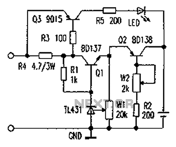
As illustrated in the figure, the lithium battery charging control board employs a constant current charging mechanism. The components Q1, R1, W1, and TL431 form a precision adjustable voltage regulator circuit. The components Q2, W2, and R2 create an...