
USB Switch For Printers

This circuit design effectively facilitates the seamless sharing of a printer between a PC and a laptop, utilizing a relay-driven approach for automatic switching. The use of standard type-B USB sockets (K1 and K2) for the PC and laptop connections ensures compatibility with most devices, while the type-A socket (K3) connects to the printer. The connection process begins with the PC being the primary device, with the relay configured to maintain this connection through its normally closed contacts.
When the laptop is connected, it sends a 5-volt signal through its USB port, which activates the relay (Re1). This relay is critical for managing the switching mechanism, as it transitions from the PC connection to the laptop connection, thereby allowing the laptop to communicate with the printer. The design emphasizes the need for short and equal-length traces for the D+ and D- signals to minimize signal degradation and ensure reliable communication.
The relay selection is important; a low-power relay rated for 5 V at 100 mA is suitable for this application, as it can effectively handle the switching without introducing significant power consumption. Additionally, the inclusion of switch S1 provides flexibility in scenarios where both computers are permanently connected, allowing for manual selection of the active device.
Overall, this circuit design is an efficient solution for users needing intermittent access to a shared printer, ensuring that both the PC and laptop can utilize the printer without the hassle of physical reconnections. The careful consideration of component specifications and layout design contributes to the reliability and functionality of the circuit.This circuit switches a printer`s USB connection from a PC to a laptop. What was needed was a method of allowing a laptop to use the printer occasionally while at all other times the printer would be connected to the PC. Instead of unplugging the printer from the PC and then into the laptop, the circuit switches the USB connection automatically.
K 1 and K2 are standard type-B USB sockets, while K3 is a USB type-A socket. The USB lead from the laptop plugs into K2 while the PC`s USB lead plugs into K1. A USB cable from K3 connects the printer to this circuit. The cable from the PC is always plugged in while the cable from the laptop is only connected whenever this device needs to print. In normal operation the laptop is not connected to K2, so the USB signal to the printer comes from the PC via K1, the normally closed contacts of relay Re1, through to K3 and from there to the printer.
Whenever the laptop is connected up, the presence of the 5-volt power signal on its USB port causes Re1 to switch over to the printer`s connection to K2 and the laptop. Unplugging the laptop returns control of the printer back to there PC. The circuit was tested on a USB 1. 1 compliant printer and a PC and laptop that had USB-2. 0 high-speed ports. The PCB traces for D+ and D should be kept as short as possible and ideally should be the same length.
The relay should be a low-power type (5 V at 100 mA coil current) with two changeover (c/o) contacts. Switch S1 is only required in situations where the two computers you want to select between are permanently present and connected up to the circuit.
The switch then selects the computer having access to the printer. 🔗 External reference
Related Circuits

This circuit is designed for differential analog circuit switches. The FM1208 monolithic dual differential multiplexer is utilized in applications where the RDS (ON) must be closely matched. The RDS (ON) for the monolithic dual multiplexer operates with a precision...
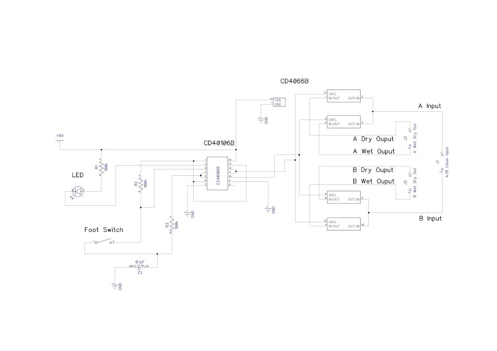
A simple audio switching circuit is experiencing issues. The circuit utilizes a CD40106 Schmitt Trigger in conjunction with a CD4066 CMOS switch to route audio signals. The circuit design incorporates a CD40106 Schmitt Trigger, which is essential for providing clean...
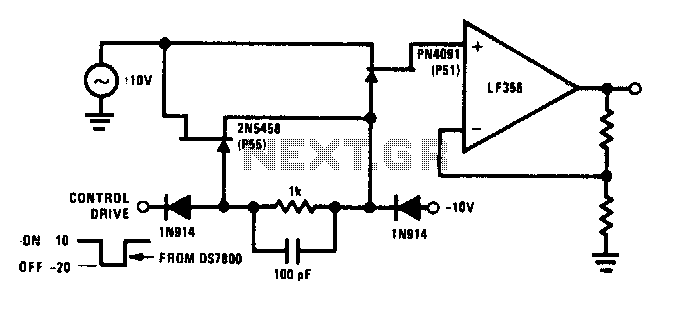
The commutator circuit delivers low impedance gate drive to the PN4091 analog switch for both on and off drive conditions. This circuit also achieves near-ideal gate drive conditions for high-frequency signal handling by offering low AC impedance during off...
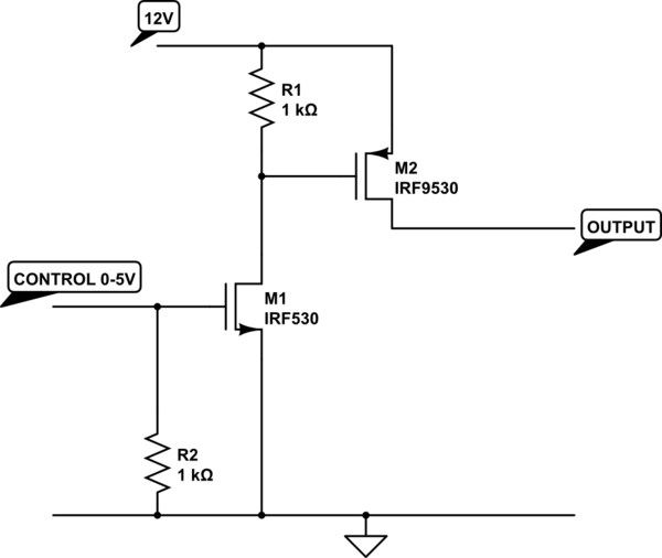
The transistor depicted is a P-channel MOSFET functioning as a high-side switch. Typically, an N-channel MOSFET is preferred for low-side switching, but the P-channel variant can be utilized effectively with the addition of a load at the drain. When...
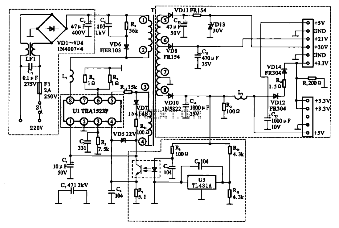
The East Shi IDS-2000F STB switching power supply circuit primarily consists of an AC input circuit, a switching oscillation circuit, an output circuit, and a secondary steady voltage control circuit. The AC input circuit includes a switch (S), fuse...
This application note describes a digital blood pressure meter concept that utilizes integrated pressure sensor analog signal-conditioning circuitry, microcontroller hardware/software, and a liquid crystal display. The sensing system measures cuff pressure (CP) and extracts pulses for analysis to determine...