
USB to RS232 Using Atmel ATtiny2313 or ATmega8
g. RS232. In addition there is a need for device drivers as software support on the PC side. Bec ause of this, RS232 based communication is still very popular among end systems manufacturers. This interface is well established and has good operating system support, but recently the physical RS232 port has been removed from the standard PC interface, giving ground to USB ports. Implementation of USB into external devices can be done in two ways: 1. By using a microcontroller with hardware implemented USB interface. It is necessary to know how USB works and write firmware into the microcontroller accordingly. Additionally, it is necessary to create a driver on the computer side, unless if the operating system includes standard USB classes.
The main disadvantage is the lack of availability of this kind of microcontrollers and their high price compared to simple RS232 microcontrollers. 2. The second option is to use some universal converter between USB and another interface. This other interface will usually be RS232, 8-bit data bus, or TWI bus. In this case there is no need for special firmware, it isn`t even necessary to know how USB works, and no driver writing is required, as the converter vendor will offer one driver for the whole solution.
The disadvantage is the higher price of the complete system, and the greater dimensions of the complete product. The solution presented in this document is a USB implementation into a low-cost microcontroller through emulation of the USB protocol in the microcontroller firmware.
The main challenge for this design was obtaining sufficient speed. The USB bus is quite fast: LowSpeed 1. 5Mbit/s, FullSpeed 12Mbit/s, HighSpeed 480Mbit/s. The AVR microcontrollers are fully capable of meeting the hard speed requirements of LowSpeed USB. The solution is however not recommended for higher USB speeds. Extensive details regarding physical USB communication can be found at the website This documentation is very complex and difficult for beginners. A very good and simple explanation for beginners can be found in the document USB in a Nutshell. Making Sense of the USB Standard written by Craig Peacock [2]. In this application note the explanation is limited in scope to understanding the device firmware. The USB physical interface consists of 4 wires: 2 for powering the external device (VCC and GND), and 2 signal wires (DATA and DATA-).
The power wires give approximately 5 volts and max. 500mA. The AVR can be supplied from the Vcc and GND. The signal wires named DATA and DATA- handle the communication between host (computer) and device. Signals on these wires are bi-directional. Voltage levels are differential: when DATA is at high level, DATA- is at low level, but there are some cases in which DATA and DATA- are at the same level, like EOP (end of packet). Therefore, in the firmware driven USB implementation it is necessary to be able to sense or drive both these signals.
According to the USB standard the signal wires must be driven high between 3. 0-3. 6V, while the Vcc supported by the USB host is 4. 4 5. 25V. So if the microcontroller is powered directly from the USB lines, then the data lines must pass through a level converter to compensate for the different voltage levels. Another solution is to regulate the Vcc supported by the host down to 3. 3V, and run the microcontroller at that voltage level. A schematic diagram of the microcontroller connection to the USB bus is shown in Figure 8. This schematic was made for the specific purpose of a USB to RS232 converter. There were also implemented specific functions as direct pin control and EEPROM read/write. The USB data lines, DATA- and DATA, are connected to pins PB0 and PB1 on the AVR. This connection cannot be changed because the firmware makes use of an AVR finesse for fast signal reception: The bit signal captured from the data lines is right shifted from LSB (PB0) to carry and then to the reception register, which collects the bits from the data lines.
PB1 is used as input signal because on 8-pin ATtiny2313. This pin can be used as external interrupt INT0. No additional connection to INT0 is necessary the 8-pin version of the AVR is the smallest pin count available. On other AVRs, an external connection from DATA to the INT0 pin is necessary to ensure no firmware changes between different AVR microcontrollers.
For proper USB device connection and signaling, the AVR running as low speed USB device must have a 1. 5k pull-up resistor on DATA-. The Vcc supplied by the USB host may vary from 4. 4V to 5. 25V. This supply has to be regulated to 3. 0 3. 6V before connecting the 1. 5k pull-up resistor and sourcing the AVR. Dimension a voltage regulator depending on the power load of the target system. The voltage regulator must be a low drop-out regulator. The schematic in Figure 8 use a LE35 regulator with a nominal output voltage of 3. 5V. But one can use any similar solution as long as the required properties are held. Even a very simple regulator based on a Zener diode could in some cases be used. The other components provide functions for proper operation of the microcontroller only: Crystal as clock source, and capacitors for power supply filtering.
This small component count is sufficient to obtain a functional USB device, which can communicate with a computer through the USB interface. This is a very simple and inexpensive solution. Some additional components can be added to extend the device functions. A TSOP1738 infrared sensor can be used to receive an IR signal. A MAX232 TTL to RS232 level converter should be added to make a USB to RS232 converter. To control LED diodes or display, they can be connect to I/O pins directly or through resistors. 🔗 External reference
Related Circuits
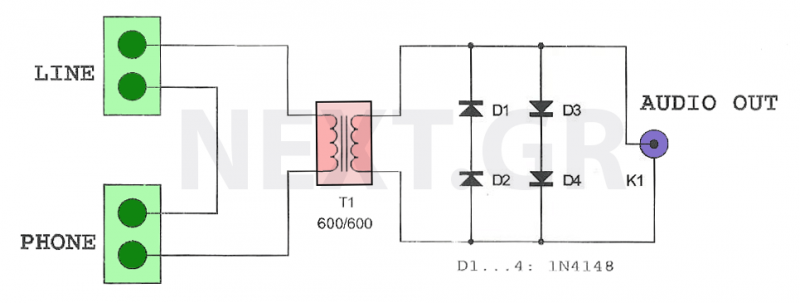
This circuit is designed to record telephone conversations on a landline telephone. It requires a small circuit and a computer subscription. Recording conversations is useful for recalling important discussions. Previously, this was accomplished using a small tape recorder, where...
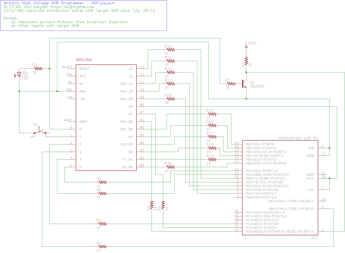
The project explains how to create a simple AVR High Voltage Programmer using Arduino. It can be utilized to fix or recover incorrectly fused AVR chips. The AVR High Voltage Programmer is designed to reprogram AVR microcontrollers that have been...
This circuit is designed for children's entertainment and can be installed on bicycles, battery-powered cars, motorcycles, as well as models and various games and toys. When switch SW1 is positioned as indicated in the circuit diagram, it generates the...
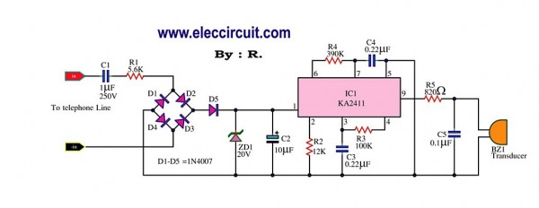
This circuit is designed to generate a loud ringing tone for an electricity bell in older telephone systems. It serves as a replacement for the original ringer that may be lost, eliminating the need for a new phone. The...
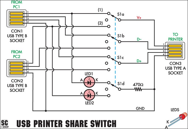
This device enables two computers to share a single USB printer or other USB devices such as an external flash drive, memory card reader, or scanner. A rotary switch is used to select the PC that will connect to...
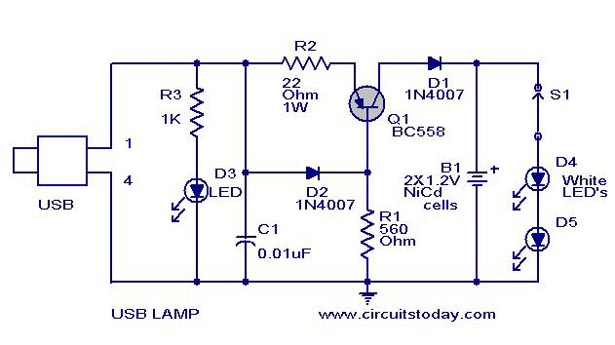
A simple USB LED lamp circuit utilizing a 5-volt power supply sourced from a USB port, designed to illuminate a desktop or laptop computer during power outages. The USB LED lamp circuit operates by converting the 5-volt DC power provided...