
USB Printer Share Switch Circuit Project

The device operates by employing a rotary switch that is mechanically linked to multiple switch poles. Each pole corresponds to a specific USB connection, allowing the user to toggle between two distinct USB sockets (CON1 and CON2) that are connected to the two computers. The selected socket's pins are routed through to a common output socket (CON3), which connects to the USB printer or device.
The inclusion of two LEDs serves as a visual indicator for the user, providing immediate feedback on which computer is currently active. The first LED (LED1) lights up when PC1 is selected, while the second LED (LED2) illuminates when PC2 is chosen. This is achieved through the fourth switch pole (S1d), which is activated in tandem with the rotary switch to ensure that the correct LED reflects the current selection.
The circuit design is straightforward and does not require a power supply, making it ideal for home use where simplicity and cost-effectiveness are priorities. Since it bypasses the need for networking, users can easily switch between computers without the complexities associated with a networked environment. This device is particularly useful for users who need to share a USB printer or device occasionally without the hassle and overhead of maintaining a dedicated print server or a network setup.
Overall, this manual USB switching device offers a practical solution for sharing USB peripherals between two computers in a home or small office environment, ensuring ease of use and flexibility without unnecessary complications.This simple device allows two computers to share a single USB printer or some other USB device, such as an external flash drive, memory card reader or scanner. A rotary switch selects the PC that you wish to use with the USB device, while two LEDs indicate the selected PC.
The most common way to share a USB printer between two PCs is to use one ma chine as a print server. However, that`s not always convenient because it means that the server PC must always be on if you want to print something. That can be a real nuisance if you just want to quickly fire up the other machine and print something out.
It also means that the two PCs must be networked together, either via a hub/router or directly via an ethernet crossover cable. Another way is to use a dedicated USB print server. However, as before, this must be connected to an ethernet network, along with the PCs. Such devices also need their own power supply, generally cost well over $100 and are overkill if you just want to share a single USB printer between two computers for occasional printing in a home set-up.
That`s where this simple device comes in. It`s basically a 2-way switch box that lets you manually switch your USB printer from one PC to the other, as required. The switching is performed using a rotary switch, while two LEDs on the front panel indicate which PC has been connected to the printer.
This method has several advantages. First, you don`t need to network your two computers. Second, you can print from either machine with the other turned off. And third, the device doesn`t need a power supply. The circuit uses switch poles S1a-S1c to select either USB socket CON1 or CON2 and connect its pins through to CON3. The fourth pole (S1d) selects either LED1 or LED2, to indicate which PC has been selected. 🔗 External reference
Related Circuits
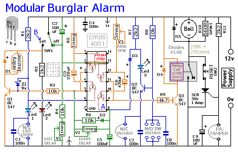
This circuit includes automatic exit and entry delays, as well as a timed bell cut-off feature. It supports both normally-closed and normally-open contacts, and incorporates a 24-hour personal attack/tamper zone. The use of expansion modules allows for the addition...
This circuit controls a small, four-phase, five-wire, unipolar stepper motor, commonly designated as the "KP4M4-001." This type of motor was utilized in many 5 1/4" floppy disk drives in older computers. Although now obsolete, such disk drives are often...
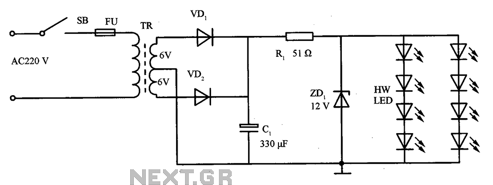
The schematic for the LED lighting circuit in a refrigerator consists of eight high-brightness white LED lights. These LEDs are housed in a transparent white plastic tube, which is the same height as the refrigerator cabinet. The circuit receives...
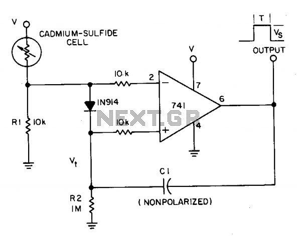
A photocell circuit provides automatic threshold adjustment. Monostable action prevents undesired retriggering of the output. With only one op amp IC, the circuit offers automatic adjustment of its trigger level to accommodate various light sources, changes in ambient light,...
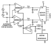
The Common Mode Rejection Ratio (CMRR) facilitates the rejection of high-frequency common-mode voltages, leading to the attenuation of elevated ambient noise levels from utility lines, industrial machinery, and other sources of radiation. The circuit diagram presented illustrates the advantages...
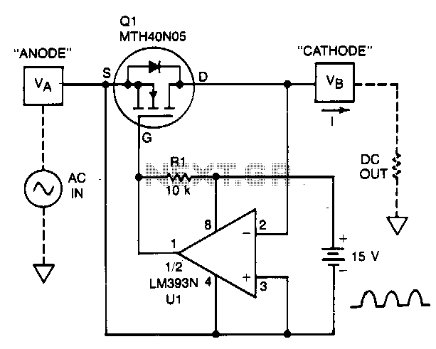
A TMOS power FET, Q1, and an LM393 comparator provide a high-efficiency rectifier circuit. When voltage V1 exceeds V2, the output of U1 becomes high, and Q1 conducts. Conversely, when V2 exceeds V1, the comparator output becomes low, and...