
Using LVDS serializer/deserializer devicesm

The LVDS interface is particularly advantageous in automotive applications due to its ability to transmit high-quality audio data over long distances with minimal interference. The differential signaling used in LVDS reduces the susceptibility to noise, making it suitable for environments with significant electromagnetic interference. The implementation of the MAX9205/MAX9206 SerDes allows for efficient data handling, ensuring that audio streams maintain integrity from source to destination.
In practical applications, the integration of the MAX9205 and MAX9206 into automotive systems can lead to enhanced audio experiences, allowing for features such as surround sound and high-fidelity playback. The design considerations for the implementation should include proper layout techniques to minimize crosstalk and ensure signal integrity. Additionally, attention should be given to the power supply design, as fluctuations in power can affect the performance of the LVDS system.
Overall, the LVDS interface, particularly with the MAX9205/MAX9206 components, represents a robust solution for modern automotive audio systems, combining high performance with cost-effectiveness and ease of integration into existing architectures. This makes it a preferred choice for manufacturers aiming to deliver superior audio quality in vehicles.Low Voltage Differential Signaling (LVDS) interface is a digital video signal transmission vehicle of the most effective interface, it is to send digital audio data stream of low-cost program. This article describes how the use of Maxim Integrated Products Inc. (Maxim) The MAX9205/MAX9206 10 bit LVDS serializer / deserializer (SerDes), through the STP cable to send up to four I2S audio data streams. Domain audio signal in analog and digital domains will reduce the quality of each conversion, so as far as possible for the audio data in digital form to get the best sound quality is very important. Transmission-oriented media system (MOST) bus for audio data transmission and vehicle design, but more expensive to implement, andfor most applications.
For consumer audio equipment, generally use S / PDIF (by SONY and PHILIPS companies co-developed a digital audio output interface) to compressed audio data transmitted from an audio device to another audio device. However, S / PDIF not be sufficient bandwidth to send uncompressed format 5. 1 or 7. 1 digital audio, but also suitable for automotive applications, the lack of a proven, robust physical layer.
The use of LVDS transmission of digital audio data is a robust, low-cost, high-bandwidth interface options that can easily be added to existing hardware, without affecting system resources. Is now available I2S digital audio data can be transferred to different parts of cars, but not actually on the software overhead.
By maintaining the audio data in digital form, the system no longer require multiple ADC, DAC and cables, which saved the cost and board space can be used to achieve other functions. LVDS has been used to from the camera, DVD player and navigation system, video data sent to the vehicle routing in a variety of display devices.
LVDS available low signal amplitude and differential structure in order to allow it to electromagnetic radiation is very low high-bandwidth data transmission. MAX9205 has been designed to send a single reference clock 10-bit parallel data. I2S signals for SCLK, WS and SDA0-3 as a data reference clock and synchronization with the SCLK at least 2 times its frequency.
MAX9205 requirements for the reference clock frequency range 16 ~ 40MHz, but the chip reference clock will be locked down to 10MHz, thus allowing the use of commonly used clock frequency of 12. 28MHz. Leave the module in the signal beam line to be very robust, able to endure the harsh automotive environment and state failure.
LVDS bus need to be AC-coupled, so as to avoid high pressure in the event of damage to short-circuit situation. Since the MAX9205 does not automatically signal to the output DC-balanced, it should be to ensure that the data to be transmitted has been DC-balanced.
10 available in the input, generally not used more than six, it can make use of the remaining four input data for the transmission of DC-balanced. And WS-signal SCLK signal is symmetric, so only on the random signal SDA0-3 to RP and feed to the unused input to be sent to ensure that dual-channel I2S each packet equal to the number of 1 and 0.
To meet the establishment and maintenance of the MAX9205 time and prevent the MAX9206 deserializer output jitter is too large, it should be in the I2S signals change state is not in its sample. Will TCLK_R / F access to GND, so that in the MAX9205 reference clock (TCLK) falling edge of the input sample.
It is assumed that the state of the SCLK rising edge of TCLK to change. If the configuration, it is necessary to TCLK_R / F be adjusted as appropriate to ensure that the input signal to meet the time requirements to establish and maintain. Right I2S input signal waveform samples shown in figure 1. Figure 2 gives the MAX9205 and MAX9206 application schematic. Left part of the serial circuit includes sending LVDS serial and audio data streams required for the circuit.
Right part of the SerDes circuit includes r 🔗 External reference
Related Circuits
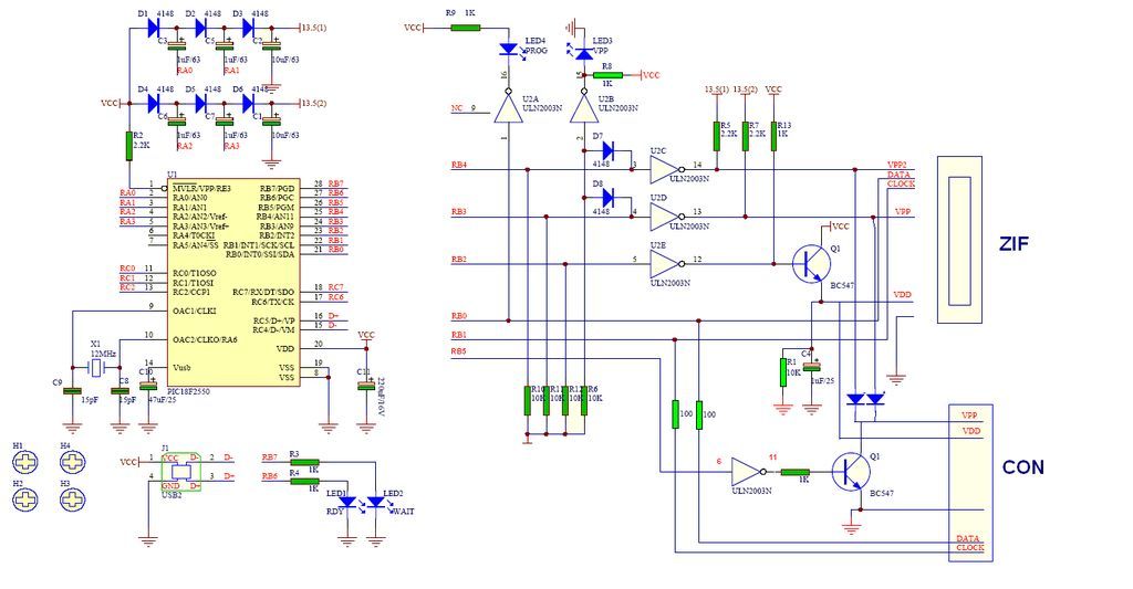
GTP USB PIC Programmer (Open Source). This project includes the GTP USB (not plus or lite). The schematic, photos, and PCB have been developed by PICMASTERS. The GTP USB PIC Programmer is an open-source device designed for programming PIC microcontrollers...
An embedded system designed for tracking and positioning vehicles utilizes the Global Positioning System (GPS) and the Global System for Mobile Communication (GSM). This project employs the AT89S52 microcontroller to interface with various hardware peripherals. The system continuously monitors...
This circuit eliminates the traditional tungsten filament lamp amplitude regulator along with its associated time constant and linearity issues. Additionally, it addresses the reliability problems commonly found with lamps. The Wien Bridge oscillator is utilized, leveraging the fact that...
The title contains numerous words because this instructable integrates various concepts from multiple sources. The primary idea originated from Robomaniac's Desktop Energy Seed Lamp, combined with Witch's Growing Plants with LED Lights instructable and various wick gardening planters. The...

This circuit is a simple metronome model designed for ease of use. It employs transistors as key components, specifically configured as an astable multivibrator, to produce a beeping sound. The tone can be adjusted using a variable resistor (VR1)....
The TDA7000 is a well-known FM radio receiver integrated circuit (IC), also referred to as a one-chip FM radio receiver. It operates within the VHF FM band, covering frequencies from 70 to 120 MHz. Introduced in the 1980s, the...