
gtp usb pic programmer open source using pic18f252

The GTP USB PIC Programmer is an open-source device designed for programming PIC microcontrollers via USB. It is important to note that this version is the standard GTP USB model, distinguishing it from the GTP USB Plus and Lite variants. The project is characterized by its accessible design, allowing users to replicate the hardware and software components.
The schematic diagram of the GTP USB PIC Programmer illustrates the interconnections between the various components, including the microcontroller, voltage regulators, and USB interface circuitry. The design typically incorporates a PIC microcontroller that manages the programming operations, interfacing with the target PIC microcontroller through a set of programming pins. The USB interface allows for easy connection to a computer, enabling the transfer of programming data.
The PCB layout is optimized for compactness and efficiency, ensuring that all components are placed in a manner that minimizes interference and maximizes signal integrity. The board is designed to accommodate standard USB connections and includes necessary decoupling capacitors to stabilize the power supply.
Photos accompanying the project provide visual references for assembly and component placement, aiding users in building their own programmers. The open-source nature of this project encourages community contributions, allowing for improvements and modifications to enhance functionality or compatibility with a broader range of PIC microcontrollers.
In summary, the GTP USB PIC Programmer represents a valuable tool for hobbyists and professionals alike, facilitating the programming of PIC microcontrollers in a user-friendly manner while promoting an open-source ethos within the electronics community.GTP USB PIC PROGRAMMER (Open Source) This work includes, GTP USB (not plus or lite) . The schematic, photos and PCB have been developed by PICMASTERS based.. 🔗 External reference
Related Circuits
The 555 timer can be utilized to reduce the cost of incorporating a triggered sweep into an economical oscilloscope. The timer is activated by the input operational amplifier of the circuit. The application of the 555 timer in an oscilloscope...
%2Busing%2Bop%2Bamp%2B741%2Bic%2B.png)
A zero crossing detector (ZCD) is a voltage comparator that switches its output between +Vsat and -Vsat (where Vsat is the saturation voltage, approximately 14V) when the input crosses the zero reference voltage. Comparators are fundamental operational amplifier circuits...
This circuit is a simple analog multiplier. The operation of the circuit can be understood by considering A2 as a controlled gain amplifier that amplifies V2, with its gain dependent on the ratio of the resistance of PC2 to...

The circuit diagram depicts a simple 24W mono amplifier utilizing the TDA1516 integrated circuit. The TDA1516 is a class B power amplifier housed in a 13-pin SIL package. This IC incorporates several protective features, including short circuit protection, load...
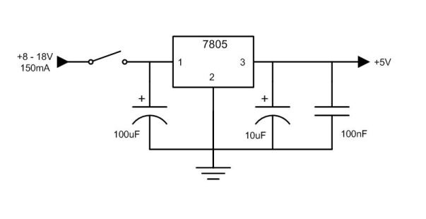
A simple 7805 charging circuit designed to recharge smartphones, such as the Incredible model. The circuit design is similar to that of the Minty Boost. The 7805 voltage regulator is a popular component used in various electronic circuits to provide...
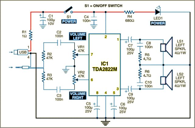
The circuit is designed as a dual audio power amplifier for use in battery-operated sound players. The TDA2822M specifications include low quiescent current, minimal crossover distortion, a supply voltage as low as 1.8 volts, and a minimum output power...