
Using the joystick port as general purpose input

The joystick button inputs serve a versatile role in electronic designs, allowing for the integration of various types of input mechanisms. These inputs can be configured to function as general-purpose buttons or switches, making them suitable for a wide range of applications, from gaming controllers to industrial control panels.
The inputs can accept signals from logic level sources, which means they are compatible with digital circuits operating at standard voltage levels, typically 3.3V or 5V. Additionally, they can interface with open collector or open drain outputs, which are common in digital logic circuits. This feature allows for the connection of multiple devices to a single input line, enabling more complex control schemes without the need for additional components.
When connecting mechanical contacts such as switches, microswitches, or pushbuttons, it is critical to note that the joystick port lacks inherent hardware debouncing capabilities. Mechanical switches can produce noisy signals when toggled, leading to multiple transitions being detected instead of a single clean signal. To mitigate this issue, external debouncing circuits may be employed. These circuits typically consist of resistors and capacitors configured to filter out the noise, ensuring that the input signal stabilizes before being processed. Alternatively, software debouncing techniques can be implemented in the firmware of the controlling microcontroller or processor, which involves programming logic to ignore rapid state changes within a specified time frame.
In summary, the joystick button inputs are adaptable components that enhance the functionality of electronic devices, but careful consideration must be given to signal integrity and debouncing when integrating mechanical switches.The joystick button inputs can be used as general purpose button or switch inputs, and can also be driven by logic level signals or by open collector or open drain logic outputs. If used with a signal direct from a mechanical contact (e.g. a switch, microswitch, contact, or pushbutton), remember that the joystick port does not perform hardware debouncing, so this must be provided by external hardware or provided by software.
🔗 External reference
Related Circuits
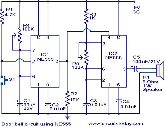
The primary components of this doorbell circuit are two NE555 timer integrated circuits (ICs). When switch S1 is pressed momentarily, the loudspeaker emits a bell tone for the duration determined by the monostable multivibrator configuration around IC1. Pressing switch...
The objective of this project was to design a compact portable mixer powered by a 9V PP3 battery, while ensuring high-quality performance. The mixer consists of three primary modules, which can be customized in quantity and arrangement to meet...
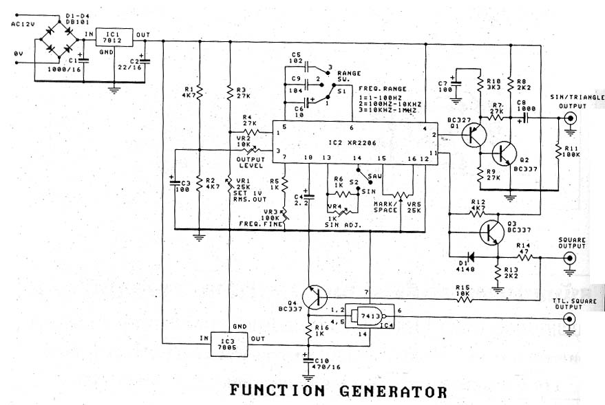
The signal generator, also known as "The Function Generator," is a device designed for use in a single machine. It is often associated with a significant cost. The function generator is a versatile electronic instrument used to generate various types...
The MSK4204RH is a radiation-hardened complete H-Bridge microcircuit designed for use in DC brushed motor control applications or Class D switch-mode amplification in space or other harsh operating environments. The internal components have been selected to withstand a total...
The ADRF6702 TxMod is an IQ modulator that includes an integrated phase-locked loop (PLL) and voltage-controlled oscillator (VCO). The PLL synthesizer employs a fractional-N PLL to produce a 2*FLO input for the I-Q modulator. The PLL reference input can...

A simple frequency meter or frequency counter circuit featuring an LCD display and an AVR microcontroller. This includes a DIY schematic circuit diagram and embedded C code. The frequency meter circuit is designed to measure the frequency of input signals...