
Using the same parameters more convenient level 36dB-oct low-pass filter design

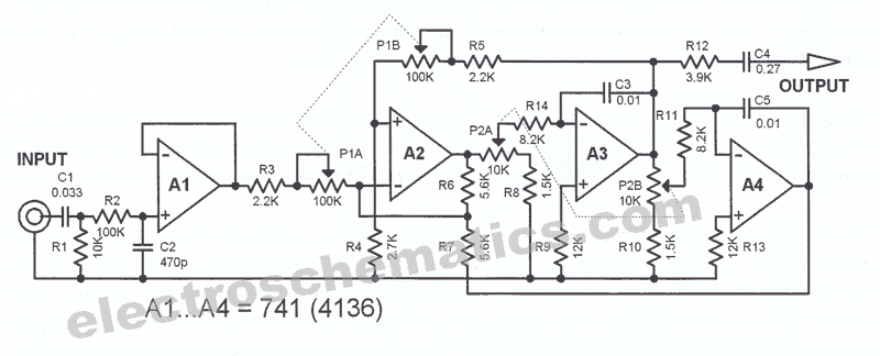
A 36 dB/octave Butterworth filter is designed to provide a smooth frequency response with minimal ripple in the passband. The filter is structured in three stages, each containing two filter sections, which allows for a gradual roll-off and enhances the overall performance of the filter. The specific frequency characteristics are critical, as they define the filter's cutoff frequency and the transition between the passband and the stopband.
Normalization of the filter response to a value of 0 is essential for maintaining consistent gain across all levels. This normalization process involves adjusting the gain settings for various operational amplifiers (A1 to A4) used within the circuit. The selected values of 0.517, 0.707, and 1.931 at port 1 indicate specific gain adjustments that must be made to achieve the desired output characteristics.
The operational amplifiers play a vital role in the feedback mechanism of the filter. The gain of each operational amplifier is influenced by the feedback resistors, which can be calculated using the provided formula. This calculation is crucial for ensuring that the filter operates within its intended parameters, allowing for effective signal processing without distortion.
The passband gain of 4.2 times indicates that the output signal will be amplified relative to the input signal. Consequently, the input amplifier A1 must be configured to have an attenuation of 1/4.2 to ensure that the overall gain remains balanced. Proper management of the series input is critical to prevent saturation, which can introduce high-frequency harmonics that the filter may not adequately suppress.
In designing the circuit, careful consideration must be given to component selection and layout to minimize interference and maintain signal integrity. The performance of the Butterworth filter is heavily reliant on the precision of the components used, as well as the accuracy of the calculated resistor values. By adhering to these design principles, the filter can achieve its intended function of providing a clean and stable output signal across the specified frequency range.36dB/ocf Butterworth filter consists of three sub-ruined structure, each stage box with two filter sections c work zdB/ocf), in order to point a 3dB frequency characteristics n ormalized to a value of 0 at all levels must be adjusted separately 0. 517,0.707,1.931 have to use port 1 when the gain of the amplifier to increase the value of the way the mouth, according to a, 3 ten thousand bamboo-level number, l, 2,3), and calculate the required gain.. OP amplifier Ai ~ A4 increase the feedback gain determined by the resistor, 4- determined after. R, can be calculated; R. ( .- 1) 10 10l, the calculation result as the circuit diagram parameters. It should be noted that: passband gain of 42, Azx As, namely the total gain of 4,2 times, the input amplifier A.
Attenuating circuit should be 1/4.2, so that A 1. If not cope Series, input increases, the background had a lot of saturated filter high harmonics filters can not filter out the complete barrier.
Related Circuits
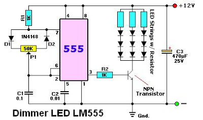
The LM555 timer IC can be utilized in various electronic projects, including the creation of an analog timer. According to the datasheet, the LM555 is versatile and can be adjusted to set timers based on specific requirements. The schematic...
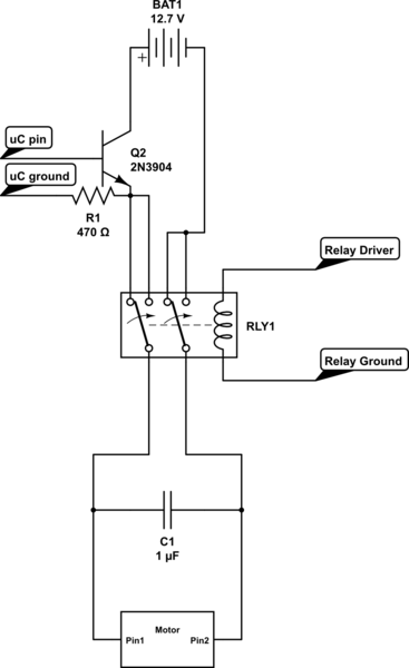
Control the state (on/off) and direction of two linear actuators that are essentially DC motors. The linear actuators operate at 12VDC and draw 10 amps of current at full load. A 25A external power supply has been purchased, as...
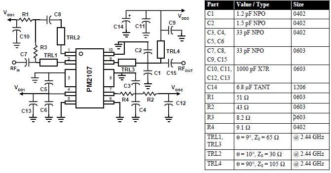
This RFIC amplifier operates in the 2400 MHz ISM band and features a two-stage design that is off-chip matched to ensure optimal performance across various applications. Powered by a 5-volt supply, the PM2107 can deliver 1 watt of saturated...
Most universal radio receivers have a very wide bandwidth that is not particularly suitable for radio amateurs. The better models with narrower bandwidth are almost a... Universal radio receivers are designed to operate over a broad frequency range, making them...
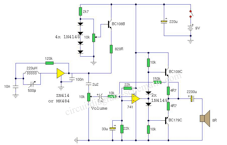
This is a circuit diagram of a portable AM radio receiver utilizing the ZN414 integrated circuit (IC), which has been replaced by the MK484, offering identical performance and pin configuration. The receiver is designed to operate within the medium...

R1 is a 15k ohm resistor. An NTC thermistor rated at 10k ohm, available at Radio Shack in the United States, is utilized. P1 is a 10k ohm potentiometer that sets the low speed (voltage) of the fans at...