
integrated circuit How do I control a two 12VDC 10A motors using an Arduino

To control two linear actuators, which are DC motors operating at 12VDC and drawing up to 10A each, a robust circuit design is necessary to handle the current requirements and enable directional control. The proposed solution involves using an H-bridge circuit for each motor, allowing for bidirectional control, and relays to manage the power supply effectively.
An H-bridge consists of four switches (transistors or MOSFETs) arranged in a bridge configuration. When the switches are activated in pairs, current flows through the motor in one direction, while activating the opposite pair reverses the current flow, causing the motor to rotate in the opposite direction. The Arduino microcontroller will send control signals to these switches, typically using PWM (Pulse Width Modulation) to control speed as well.
In addition to the H-bridge, relays can be incorporated to handle the high current drawn by the motors. The relay acts as an electromechanical switch that can be controlled by the Arduino. When the relay is activated, it connects the power supply to the H-bridge, allowing the motors to receive the necessary current without overloading the Arduino.
The circuit can be designed as follows:
1. **Power Supply**: A 25A, 12VDC power supply is connected to the H-bridge inputs.
2. **H-Bridge Configuration**: Two H-bridge circuits are constructed, one for each motor. Each H-bridge consists of four MOSFETs (or transistors) that are controlled by the Arduino.
3. **Arduino Control**: The Arduino sends signals to the gates of the MOSFETs based on desired motor direction and speed. This can be done using digital pins for direction and PWM pins for speed control.
4. **Relay Integration**: A relay module is connected to the Arduino, which activates the relay when the motors are supposed to operate. The relay connects the power supply to the H-bridge, allowing the motors to draw the necessary current.
5. **Protection Components**: It is advisable to include flyback diodes across the motor terminals to protect the circuit from voltage spikes generated when the motors are turned off.
A schematic diagram would illustrate these components clearly, showing the connections between the Arduino, H-bridges, relays, and power supply. This setup not only provides control over the actuators but also ensures that the Arduino operates within its safe current limits while allowing for the necessary power to be delivered to the motors.Control the state (on/off) and direction of two linear actuators that are really just DC motors. It seems easy but the problem is that the linear actuators are each 12VDC and consume 10 amps of current at full load. I bought a 25A external power supply because obviously the arduino microcontroller cannot not provide that much current.
I saw something about using an H bridge to control each motor`s direction and then I read something about using a relay that acts as an electromechanical switch to draw current from the power supply. Can someone help me out or draw me a circuit diagram of what this looks like so I could be able to put it together I would love to know how all of this works and I know it is probably challenging to beging electronics with but I am willing to learn as much as I can about this stuff.
🔗 External reference
Related Circuits
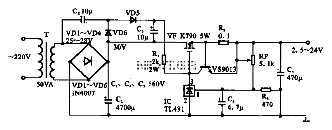
An adjustable DC power supply circuit is presented, consisting of a step-down transformer (T), a rectifier bridge (VD1 to VD4), and additional components. The voltage regulator circuit includes an adjustment potentiometer (RP, 5.1 kΩ), allowing the output voltage to...
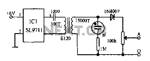
The electronic frostbite treatment instrument ASIC SL9711 consists of an oscillation circuit, a power amplifier, and a controller. It generates a sine wave at frequencies of 100 Hz and 3 Hz, followed by a step-up transformer with potentiometer adjustment...
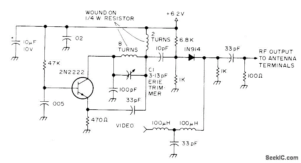
Developed as an interface between the General Instruments AY-3-8500-1 TV game chip and the antenna terminal of a TV set. Adjust capacitor C1 to the frequency of an unused channel to which the receiver is set for playing games....

This shadow alarm circuit can detect a moving shadow in a confined area, providing protection against theft. When an individual approaches the unit, it triggers a loud alarm to deter the theft attempt. The circuit leverages the light-sensing characteristics...
The schematic presented illustrates a 5A H-Bridge Module designed for the operation of a single Bipolar DC motor. The H-Bridge Module includes a header set (J2) and a connector terminal set (J1). Below is the pinout description for the...
Examples of an OFDM modulation system. The graph illustrates the input data signal (.... --- Ol01100) and the data signal by the string. The input signal is separated into components such as "00", "ll", "10", "00", "01", and other...