
UUS 65 - 73 MHz FM Transmitter

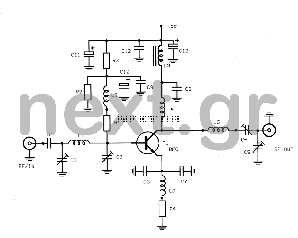
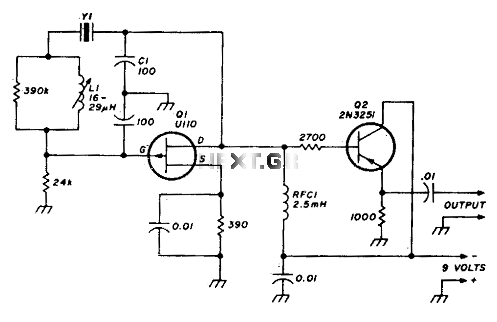
The UUS 65-73 MHz FM transmitter circuit is designed to operate within the specified frequency range of 65 to 73 MHz. This circuit can function effectively as an oscillator, producing a stable frequency output suitable for FM transmission.
The key components typically included in this schematic are a transistor, capacitors, resistors, and an inductor, which collectively form the oscillator circuit. The transistor acts as the main amplifying element, while the inductor and capacitor create a resonant tank circuit that determines the operating frequency.
The circuit may also include a power supply section that provides the necessary voltage and current to the components. A typical configuration might involve a 9V battery or a regulated power supply.
In practical applications, the output from the oscillator can be connected to an antenna for transmission purposes. The antenna design is crucial as it influences the range and quality of the transmitted signal. A simple dipole or a quarter-wave monopole antenna can be used, depending on the desired transmission characteristics.
To ensure optimal performance, it is important to consider factors such as component tolerances, layout, and shielding, which can affect the circuit's stability and frequency accuracy. Proper tuning of the inductor and capacitor values may be required to achieve the desired frequency within the 65-73 MHz range.
Overall, this FM transmitter circuit serves as a foundational design for various applications, including educational projects, hobbyist experiments, and basic communication systems within the specified frequency band.A basic UUS 65 73 MHz fm transmitter circuit schematic which can be used as UUS oscillator with no explanation 65 - 73 MHz transmitter ( oscillator ) c.. 🔗 External reference
Related Circuits
This schematic illustrates an infrared (IR) transmitter circuit utilizing an integrated circuit (IC). The circuit employs the widely recognized NE555 timer IC, which operates as an astable multivibrator to generate a signal with a frequency of 38 kHz. The...
This is a variation of the Electron Coupled Oscillator (ECO) circuit, pioneered by Dow in 1931. Dow's ECO has the screen grounded for RF. In this circuit, filament-type tubes are used instead of heater-cathode types, eliminating the need for...
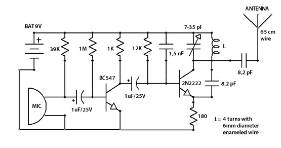
Here is a very simple, inexpensive and interesting project which provides lot of fun to a home experimenter or hobbyist. This simple transmitter can transmit speeches or songs within a short range. The circuit uses only one transistor. The...
This structure is a radio frequency (RF) amplifier designed for small UHF TV transmitters, operating within the UHF channel range of 450-800 MHz. The amplifier enhances video signals in this frequency range and operates in Class A, utilizing the...
A stable variable crystal oscillator (VXO) utilizing 6- or 8-MHz crystals employs a capacitor and an inductor to facilitate frequency pulling on either side of series resonance. The described circuit operates as a variable crystal oscillator, which is crucial in...
This simple-to-assemble FM transmitter can effectively transmit voice signals over an impressive range. By adjusting the trimmer, the signal can be heard on a nearby radio. The transmitter operates within a frequency range of 88-108 MHz and has a...