
Miniature MW Transmitter

The described circuit operates as a basic AM (Amplitude Modulation) transmitter, primarily designed for educational purposes and experimentation. The core of this transmitter is a single transistor, which serves as the oscillator and modulator. The circuit typically includes a few passive components such as resistors, capacitors, and an inductor to form the necessary tank circuit that generates the carrier frequency.
The assembly begins with the careful placement of components on a prototyping printed circuit board (PCB). The transistor is connected in a common emitter configuration, allowing it to amplify the input audio signal, which can be sourced from a microphone or an audio output device. The audio signal modulates the carrier wave generated by the tank circuit, which consists of a capacitor and an inductor.
A telescopic antenna is attached to the circuit, which enhances the transmission range by radiating the modulated signal into the surrounding environment. The transmitter's output frequency can be adjusted by varying the capacitance of the gang condenser, which is part of the tuning circuit. This adjustment is crucial for ensuring that the transmitter operates on a frequency that does not interfere with existing radio broadcasts.
To test the transmitter, a medium wave (MW) radio receiver is placed approximately one meter away from the transmitter. The radio should be tuned to an empty frequency where no stations are broadcasting, allowing the user to hear the transmitted signal clearly. When the transmitter is powered on, the audio signal will create a hissing sound on the radio until it is properly tuned to the transmitter's frequency.
This project not only serves as an introduction to basic electronics but also provides practical experience in assembling circuits, understanding modulation techniques, and exploring radio frequency transmission. Safety precautions should be taken to ensure compliance with local regulations regarding radio transmission, as unauthorized transmission can lead to legal issues.Here is a very simple, inexpensive and interesting project which provides lot of fun to a home experimenter or hobbyist. This simple transmitter can transmit speeches or songs within a short range. The circuit uses only one transistor. The entire circuit can be easily assembled on a prototyping printed circuit board. After assembling all the components properly put the whole assembly in a plastic enclosure provided with a telescopic antenna.
Now keep your MW radio and the transmitter on a table about one meter away from each other. Switch on the radio receiver and turn to a clear spot where no broadcasting station is present. Now switch on the transmitter and turn the gang condenser. At some position loud hissing sound will be heard from your receiver. 🔗 External reference
Related Circuits
The operation of the 6CL6 transmitter is quite sophisticated despite the simple appearance of the circuit. The core of the circuit is the electron-coupled crystal oscillator. This circuit integrates the functions of an oscillator and amplifier into a single...
There are many alarm systems available, but building a custom one may be appealing. This project can be assembled using affordable components that are easily accessible. The alarm transmitter module features a delayed trigger and an automatic turn-off function,...
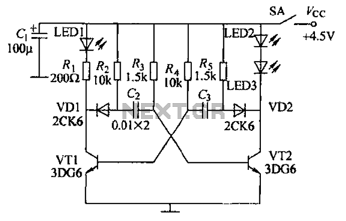
Transistors VT1, VT2, and associated RC components are configured to form a multivibrator. The multivibrator operates with resistors Ra and R4 serving as base bias resistors for VT2 and VT1, respectively. When the switch SA is closed after applying...

This FM transmitter circuit is simple and provides acceptable transmission. The signal transmitted from this FM transmitter circuit can be received at... This FM transmitter circuit utilizes a few basic components to generate frequency-modulated signals suitable for short-range transmission. The...
This circuit illustrates a 6-12 channel TV transmitter coupling circuit diagram. It is designed to stabilize the 10 P operation within the 6-12 channel range. The 6-12 channel TV transmitter coupling circuit is essential for ensuring stable transmission across multiple...

This is a small battery-operated tracking transmitter that broadcasts a repeating radio signal detectable by a directional antenna. The transmitter emits an isotropic signal across the FM band, specifically between 87 to 108 MHz. An ordinary FM radio can...