
Vanda F-9500A preamplifier b

The circuit depicted in Figure 3-2 (b) integrates a complex arrangement of power and pre-amplifiers utilizing transistors VT17 through VT31. Each transistor serves a specific role in amplifying the audio signal, ensuring that the output maintains fidelity and clarity. The design mirrors that of operational integrated circuit IC2, emphasizing a consistent approach to signal processing within the system.
The series insertion of the tone control circuit allows for precise adjustments to the audio output. The two-bit access control switch provides flexibility, enabling the user to toggle the tone control functionality on or off. This feature is crucial for applications where audio characteristics need to be tailored to specific requirements or environments.
The additional stage amplifier is linked to the final amplifier's volume potentiometer, ensuring that the audio levels can be finely tuned. The integration of an RC network facilitates the recording interface, which is essential for connecting to external devices or additional processing units. The common amplifier circuit supports both high-pass and low-pass filters, allowing for a versatile range of output configurations. The four output options provide adaptability for various audio systems, making this circuit highly functional in both professional and consumer audio applications.
Overall, the design exemplifies a sophisticated approach to audio amplification and control, ensuring high-quality sound reproduction through careful engineering of each component within the circuit.Figure 3-2 (b) is the second half of the circuit, VT17 ~ VT31 group into power amplifiers, pre-amplifiers, and it is a structure composed of exactly the same oIC2 its zero serv o circuit. Before and after class is inserted in series between the amplifier and attenuated tone control circuit, and a two-bit access control switch, it can control the tone Zouren circuit or not formed around through-o-stage amplifier in the final amplifier volume potentiometer via tone circuit Rong) 5 and RC network consisting of a recording o interfaces, common (connected amplifier circuit), high-pass, low-pass four outputs
Related Circuits
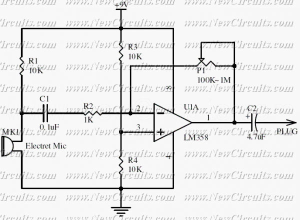
This circuit will be useful if you have an electret microphone that produces a low audio (sound) level and you want to connect it to an amplifier or something like it. The circuit boosts the microphone output voltage to...
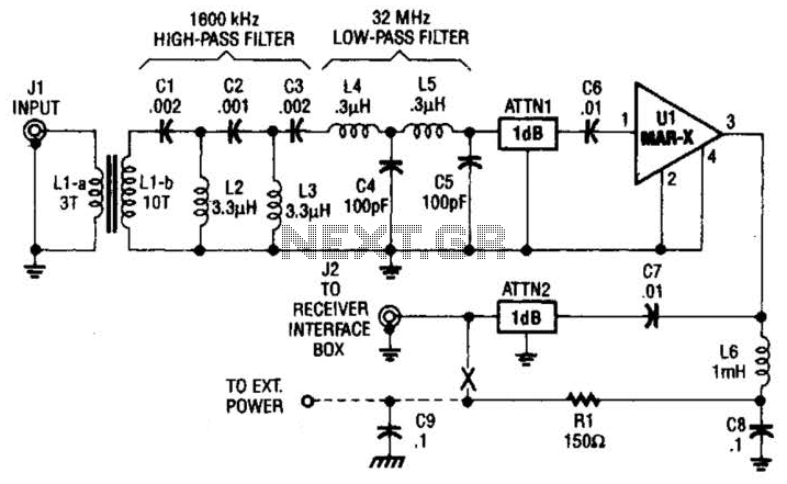
This high-frequency shortwave receiver preamplifier consists of a broadband toroidal transformer (LI-a and Ll-b), a complex LC network that includes a 1600 kHz high-pass filter and a 32 MHz low-pass filter, inductors L2 and L3 (26 turns of #26...

A Field Effect Transistor (FET) is an amplifying device where the output current is influenced by the input voltage. The FET preamplifier described here is sensitive. The Field Effect Transistor (FET) operates by utilizing an electric field to control the...
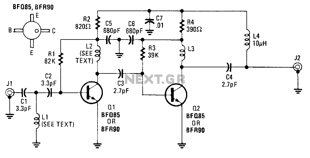
An inexpensive antenna-mounted UHF-TV preamplifier can add more than 25 dB of gain. The first stage of the preamplifier is biased for optimum noise performance, while the second stage is optimized for maximum gain. Additional details include Ll and...
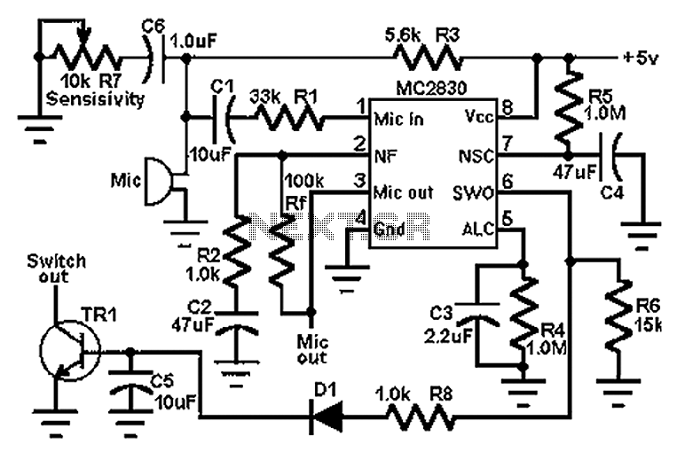
The circuit schematic utilizes the MC2830 voice circuit. Traditional voice circuits are unable to differentiate between speech and noise in the input signal. In noisy environments, such as those caused by switches, this limitation is significant. To address this...
This circuit is primarily designed to provide a microphone input for standard home stereo amplifiers. Utilizing a battery supply minimizes the risk of low-frequency hum interference from mains power, simplifying the connection to the amplifier by eliminating the need...