
Variable Frequency And Duty Cycle Oscillator

The discrete oscillator circuit is designed to produce oscillations with adjustable frequency and duty cycle, making it versatile for various applications. The core of the circuit typically includes components such as resistors, capacitors, and transistors or operational amplifiers configured to create feedback loops that sustain oscillation.
The frequency of oscillation can be altered by varying the values of the resistors and capacitors in the timing network. For instance, increasing the capacitance or resistance will generally lower the frequency, while decreasing these values will raise the frequency. The duty cycle, which defines the proportion of one cycle in which the output is active, can also be adjusted by modifying the charge and discharge paths of the timing capacitor.
In practical applications, this type of oscillator can be used in signal generation for audio applications, clock pulses for digital circuits, or modulation signals in communication systems. The output waveform can be a square wave, triangle wave, or sawtooth wave, depending on the specific configuration of the circuit components and the desired application.
To ensure stability and performance, it is crucial to select components with appropriate tolerances and characteristics, especially in high-frequency applications where parasitic capacitance and inductance can significantly affect circuit behavior. Additionally, power supply decoupling may be necessary to maintain consistent performance under varying load conditions.
Overall, the discrete oscillator circuit offers a flexible solution for generating variable frequency and duty cycle signals suitable for a wide range of electronic applications.A discrete oscillator circuit shown in the schematic diagram below is? a variable duty cycle and variable frequency oscillator, can be used to produce. 🔗 External reference
Related Circuits
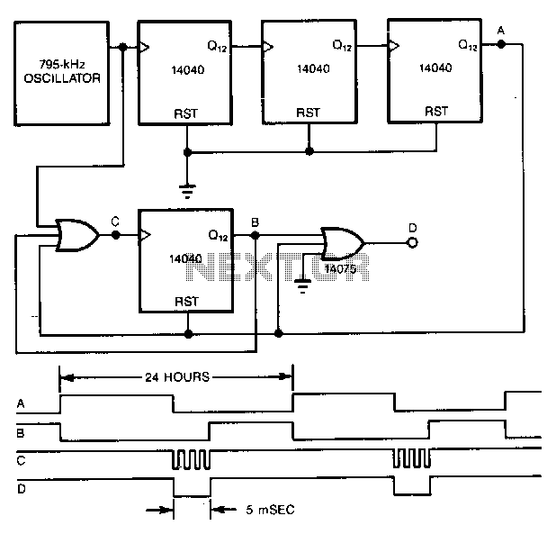
A precise pulse generator can be constructed using a precision oscillator and several CMOS counters. The number of counters can be increased to extend the pulse period as needed. This circuit will generate a pulse approximately 5 ms long...
The 32-kHz low-power clock oscillator provides several advantages compared to traditional oscillator circuits that utilize a CMOS inverter. These inverter circuits often exhibit issues such as significant fluctuations in supply currents across a 3V to 6V supply range, making...
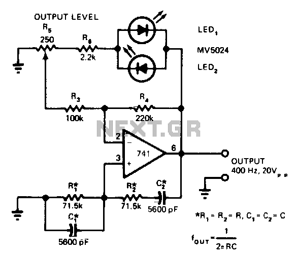
LEDs function as both pilot lamps and as an AGC (automatic gain control) in this unconventional amplitude-stabilized oscillator. The circuit utilizes Light Emitting Diodes (LEDs) for dual purposes, acting as pilot lamps to indicate operational status and as components in...
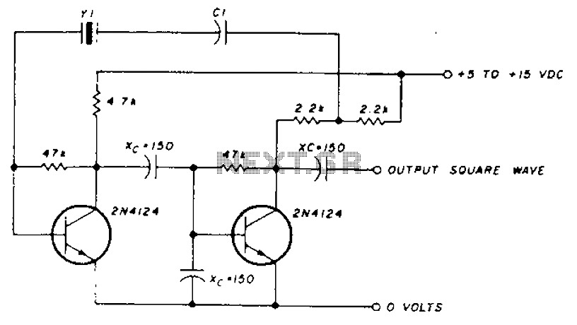
A transistor in series with capacitor C1 can be utilized to adjust the oscillator output frequency. The frequency may vary with changes in capacitance ranging from 20 pF to 0.01 µF, or as determined by the tuning capacitor. The...
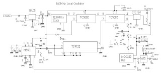
This 860 MHz Phase Locked Loop (PLL) oscillator circuit is designed for a 1200 MHz transverter's local oscillator with 435 MHz rigs. The oscillator utilizes Toshiba PLL synthesizer integrated circuits (ICs). The TC9122P serves as a preset counter for...
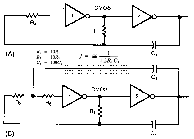
The common clock oscillator illustrated in Fig. 68-19A has two minor issues: it may not oscillate if the transition regions of its two gates differ. If it does oscillate, it might occasionally operate at a slightly lower frequency than...