
Very Low Power 32kHz Oscillator

The circuit operates effectively as a low-power clock oscillator, making it suitable for battery-operated devices where energy efficiency is critical. The use of a single transistor in the oscillator configuration simplifies the design while maintaining reliable performance. The choice of a quartz crystal ensures precise frequency stability, which is essential for timing applications. The feedback mechanism involving the load capacitors is crucial for sustaining oscillations and achieving the desired frequency of operation.
The MAX931 comparator is a key component in this design, providing a stable reference voltage that enhances the reliability of the oscillator. Its low power consumption further contributes to the overall efficiency of the circuit. The output capabilities of the comparator allow it to drive various loads, making it versatile for different applications.
In scenarios where high-speed switching is necessary, the inclusion of the 74HC14 Schmitt trigger can mitigate the effects of slower rise and fall times from the comparator output. This addition ensures that the logic levels are clean and can interface effectively with high-speed digital circuits without introducing excessive power consumption.
Overall, this 32-kHz low-power clock oscillator circuit is a robust solution for applications requiring low current draw and reliable timing, making it an excellent choice for modern electronic designs.The 32-kHz low-power clock oscillator offers numerous advantages over conventional oscillator circuits based on a CMOS inverter. Such inverter circuits present problems, for example, supply currents fluctuate widely over a 3V to 6V supply range, while current consumption below 250 µA is difficult to attain.
Also, operation can be unreliable with wide variations in the supply voltage and the inverter`s input characteristics are subject to wide tolerances and differences among manufacturers. The circuit shown here solves the above problems. Drawing just 13 µA from a 3V supply, it consists of a one-transistor amplifier/oscillator (T1) and a low-power comparator/reference device (IC1).
The base of T1 is biased at 1. 25 V using R5/R4 and the reference in IC1. T1 may be any small-signal transistor with a decent beta of 100 or so at 5 µA (defined here by R3, fixing the collector voltage at about 1 V below Vcc). The amplifier`s nominal gain is approximately 2 V/V. The quartz crystal combined with load capacitors C1 and C3 forms a feedback path around T1, whose 180 degrees of phase shift causes the oscillation.
The bias voltage of 1. 25 V for the comparator inside the MAX931 is defined by the reference via R2. The comparator`s input swing is thus accurately centred around the reference voltage. Operating at 3 V and 32 kHz, IC1 draws just 7 µA. The comparator output can source and sink 40 mA and 5 mA respectively, which is ample for most low-power loads. However, the moderate rise/fall times of 500 ns and 100 ns respectively can cause standard, high-speed CMOS logic to draw higher than usual switching currents.
The optional 74HC14 Schmitt trigger shown at the circuit output can handle the comparator`s rise/fall times with only a small penalty in supply current. 🔗 External reference
Related Circuits
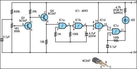
This design integrates power-on and low-battery indication features, capable of operating with any battery voltage up to 15V. It exhibits a very low current drain of 2mA or less. The circuit design incorporates a power-on indicator that activates when the...
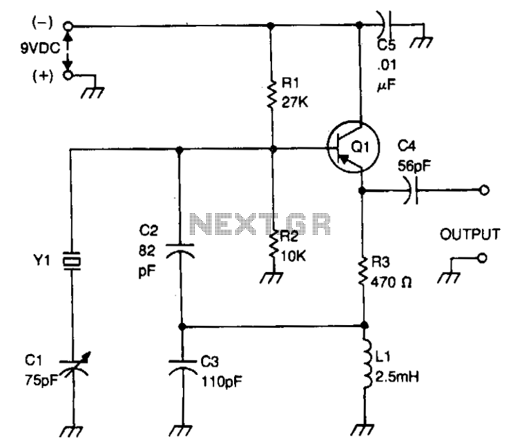
Bias for the PNP bipolar transistor is supplied by a resistor voltage divider network consisting of resistors R1 and R2. The collector of the oscillator transistor is maintained at AC ground through a capacitor C5, which is positioned near...
C1 = 100 nF multilayer or ceramic capacitor; C2 = 4.7 pF ceramic capacitor; C3 = 100 nF ceramic capacitor (1 nF or 10 nF can also be used); C4 = 40 pF trimmer capacitor; C5 = 4.7 pF...
This audio amplifier design utilizes two LM3886 chips per channel in a parallel configuration, based on the PA100 parallel amplifier detailed in National Semiconductor's application note AN1192. The amplifier can deliver approximately 50W into an 8-ohm speaker and 100W...
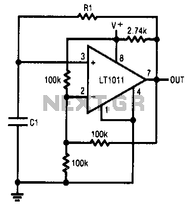
This simple RC oscillator utilizes a medium-speed comparator with hysteresis and feedback through R1 and C1 as timing elements. The frequency of oscillation is theoretically independent of the power supply voltage. Additionally, the comparator swings to the supply rails...
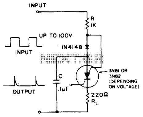
A positive-going input charges capacitor C through the IN4148 diode and resistor R. The diode ensures that the silicon-controlled switch (SCS) remains off. A negative-going input provides anode-gate current, which triggers the SCS, allowing capacitor C to discharge through...