
Variable zener diode

The described circuit functions as a voltage regulator, utilizing a zener diode to maintain a stable output voltage despite variations in input voltage or load conditions. The configuration includes a voltage divider made up of resistors R1 and R2, which sets the base voltage for the transistor. The transistor acts as a switch or amplifier, enabling or controlling the flow of current based on the voltage across the zener diode.
The adjustable stabilizing voltage, achieved by altering the resistance of R2, allows for flexibility in applications requiring different voltage levels. The current through the voltage divider is designed to be significantly higher than the base current of the transistor to ensure reliable operation and quick response to changes in load. This design consideration minimizes the risk of the transistor entering saturation, which could lead to voltage fluctuations.
The total current drawn by the circuit is a critical parameter, as it must remain within the safe operating limits of the components involved, particularly the zener diode. The maximum dissipation rating of the zener diode dictates the upper limit of the current, ensuring that the device does not overheat and fail. In this instance, with a 250 mW zener diode, the circuit is designed to operate effectively up to the specified current threshold of 50 mA.
In summary, this circuit provides a robust solution for applications requiring a stable voltage supply across a range of conditions, with adjustable output and careful consideration of component ratings to ensure reliable performance.The circuit behaves like a zener diode over a large range of voltages. The current passing through the voltage divider R1-R2 is substantially larger than the transistor base current and is in the region of 8 mA. The stabilizing voltage is adjustable over the range 5-45 V by changing the value of R2. The total current drawn by the circuit is variable over the range 15 mA to 50 mA This value is determined by the maximum dissipation of the zener diode. In the case of a 250 mW device, this is of the order of 50 mA.
Related Circuits
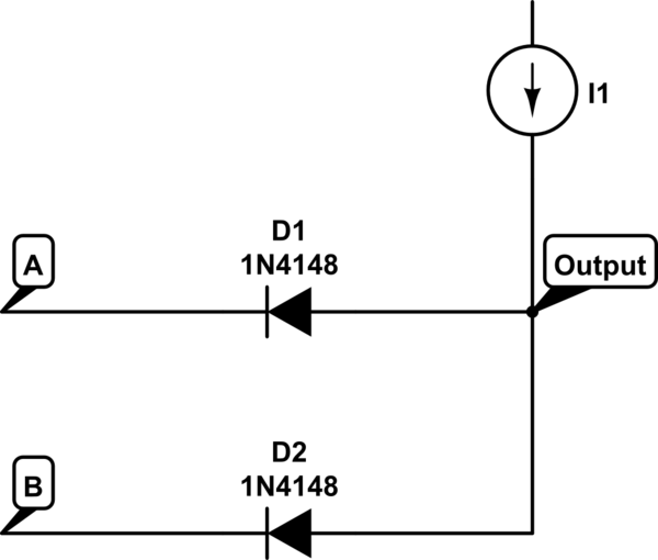
The voltage at the anode and cathode of the diodes is checked to determine whether they are conducting. There is confusion regarding the current source and how to determine the state of the diodes for input combinations (00, 01,...
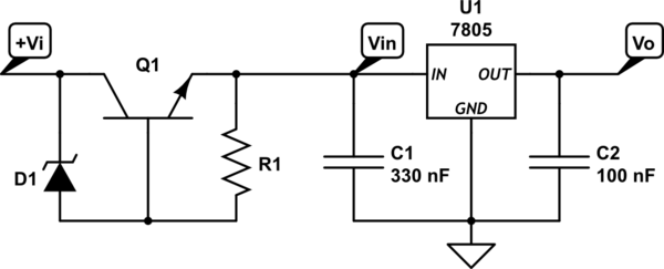
A power supply circuit is designed to convert 24VAC to 5VDC. An L7805CV voltage regulator is used; however, after rectification with a bridge rectifier and smoothing with a 33µF electrolytic capacitor, the input voltage remains at 40V peak, which...
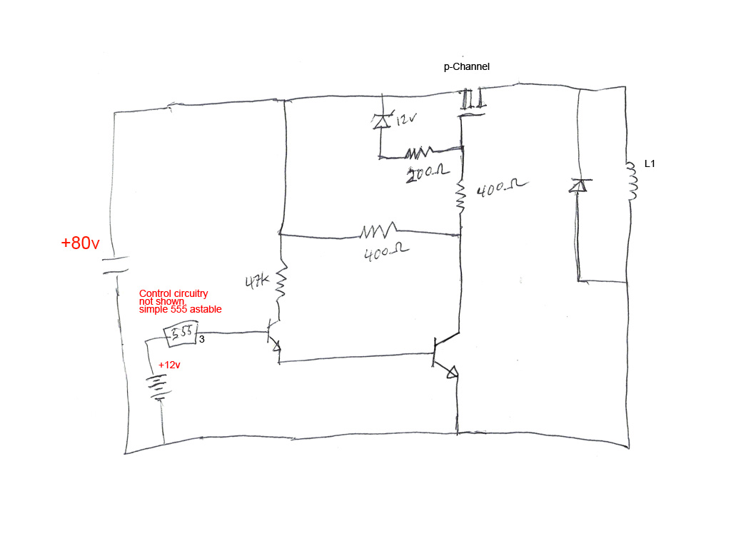
The circuit's premise involves powering an L1 coil with square pulses. A freewheeling diode is included to manage the back EMF field collapse, thereby protecting the circuitry. Previous experiments indicated that using an N-channel MOSFET on the high side...
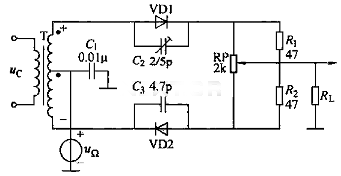
A common diode balanced modulator circuit is illustrated. It comprises two identical performance diodes and a center-tapped transformer configuration. The diodes used are VD1 and VD2, specifically 2AP9 models. The parameters for the circuit elements are detailed in FIG....
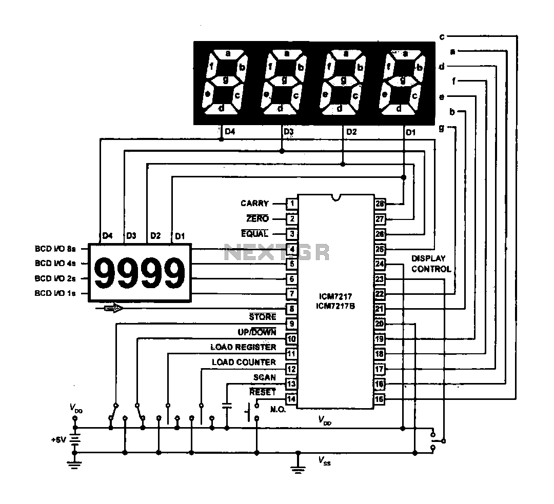
The circuit drives the light-emitting diode in a digital display configuration. The count signal is fed into the ICM7217 chip, which processes the count and subsequently drives the digital display board. The connection between the thumbwheel switches is illustrated...
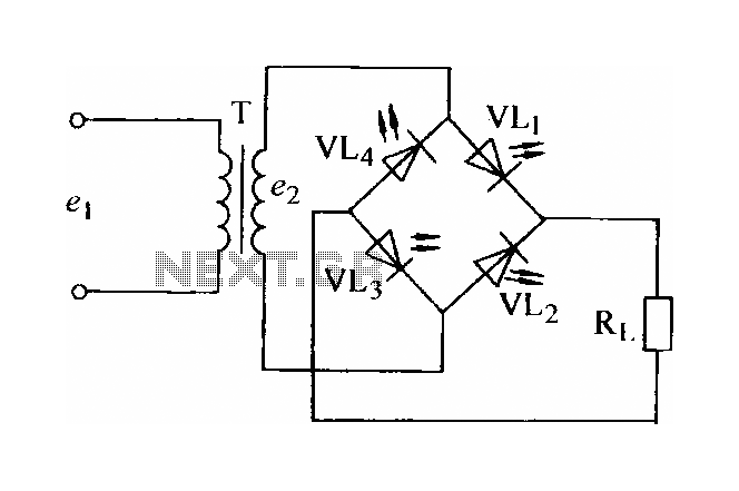
In certain applications, the current from a non-rectified voltage power supply circuit is insufficient. A light-emitting diode (LED) rectifier circuit can be employed to address this issue, serving as a power indicator. It is important to ensure that the...