
Vary the Volume of a Buzzer

The circuit design incorporates a buzzer, a potentiometer, and a power supply. The potentiometer serves as a variable resistor, allowing for the adjustment of resistance in the circuit. The buzzer is connected in parallel to the potentiometer, with the power supply providing the necessary voltage and current for operation.
When the potentiometer is set to a low resistance, the current flowing through the circuit is maximized, which energizes the buzzer to produce sound at its highest volume. The relationship between resistance and sound output is linear within the specified range. As resistance increases, the current decreases, leading to a reduction in sound output. This behavior can be graphically represented, showing the inverse relationship between resistance and sound amplitude.
In practical applications, similar circuits are utilized in audio devices where volume control is required. The design can be expanded to include additional components such as capacitors for noise filtering or diodes for protection against reverse polarity. This basic understanding of volume control through resistance manipulation can be applied to various electronic sound output devices, enhancing the user experience by providing adjustable sound levels.This is a pretty simple project we are going to do. We are going to create a simple buzzer circuit where we can increase or decrease the volume of the sound that the buzzer outputs. Okay, now we can do this in two ways. We can first turn the potentiometer all the way to the side where it gives out almost 0G of resistance.
When we start at near 0G , the sound of the buzzer will be the loudest it will ever be, since the potentiometer`s resistance is the lowest at this point; thus, at this point, the circuit outputs the greatest amount of current which is fed into the buzzer. Now as you turn the the potentiometer so that the resistance increases, you slowly begin to hear the sound of the buzzer get lower and lower.
Eventually at around 450G , you cannot hear the sound of the buzzer anymore. It dies out. The resistance of the circuit now is higher and the buzzer doesn`t receive enough current to play out sound. Similarly, we can start with the buzzer turned all the way to the side where it gives out 10KG . When you start at 10KG resistance, the buzzer does not output any sound, so you hear nothing. This is because the resistance of the circuit is too high, so the current is very low and is not sufficient to drive sound out of the buzzer.
Now as you turn the potentiometer so that the resistance decreases, you eventually hear the sound of the buzzer. This occurs at about 450G . As you keep turning it more, you hear the sound louder and louder. Turned all the way to the side so that the resistance of the potentiometer is near 0G , you hear the buzzer the loudest.
This is the way all volume sound manipulation occurs in hardware. This is the same way the volume of speakers are adjusted. So congratulations, you now know how to vary the volume of sound-outputting devices. 🔗 External reference
Related Circuits
Automatic volume adjustment with ambient noise control circuit. In car stereos and similar devices, the ambient noise level varies during high-speed and low-speed driving or while stationary, leading to different volume requirements. A fixed volume adjustment method may negatively...
Assistance is requested for a project involving audio volume control utilizing 40 relay-operated L-pad attenuators for each stereo channel. Control will be sequentially assigned to the relay. The proposed circuit design focuses on creating an advanced audio volume control system...
The MSK4204RH is a radiation-hardened complete H-Bridge microcircuit designed for use in DC brushed motor control applications or Class D switch-mode amplification in space or other harsh operating environments. The internal components have been selected to withstand a total...
Utilizing a dual polarity power supply (+-5V is suitable) can resolve most clipping issues. It is necessary to consult the data sheet for the appropriate pins to connect the voltages. A dual polarity power supply is essential in many electronic...

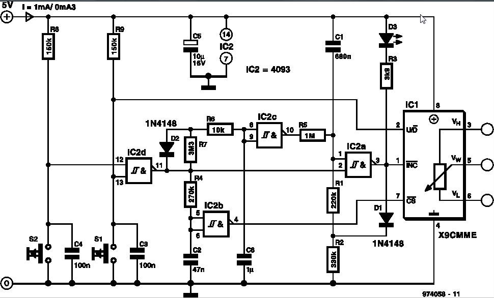
The core component of this digital volume controller (DVC) circuit is the IC2 4067, which is a 16-channel analog multiplexer. A 1kΩ resistor is connected between each input and output, allowing the multiplexer to function similarly to a potentiometer....
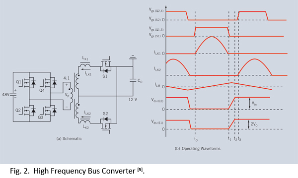
Distributed power systems are commonly used in telecommunications, networking, and high-end server applications, utilizing a 48 V bus voltage derived from the telecom industry. This 48 V bus supplies several isolated point-of-load (POL) converters that power the end loads,...