
electronic volume control

The proposed circuit design focuses on creating an advanced audio volume control system that leverages relay-operated L-pad attenuators. Each stereo channel will incorporate 40 individual attenuators, enabling precise control over audio levels. The L-pad configuration consists of resistors arranged to form a voltage divider, allowing for variable attenuation of the audio signal.
The relay system will facilitate the selection of different attenuation levels by engaging specific combinations of the L-pad attenuators. Each relay can be controlled by a microcontroller or a dedicated control circuit, which will manage the switching sequence to ensure smooth transitions between different volume levels.
To implement this design, a microcontroller with sufficient I/O pins to control all 80 relays (40 per channel) is required. The relays should be rated for the audio signal's voltage and current to avoid distortion or damage. Additionally, it is essential to incorporate debounce logic in the control software to prevent unintended relay activation due to noise or signal fluctuations.
Power supply considerations must also be addressed, as the relays will require a separate power source to operate effectively without interfering with the audio signal. It is advisable to use a regulated power supply to ensure stable operation.
In terms of layout, careful attention should be given to the placement of components on the PCB to minimize interference and maintain signal integrity. Shielding may be necessary to protect sensitive audio signals from external noise sources. Overall, this project presents an opportunity to develop a sophisticated volume control system that enhances audio performance through precise relay-based attenuation.Anyone able to help? The plan is an audio volume control using 40 relay-operated L-pad attenuators per stereo channel. Control is passed in succession to the relay a.. 🔗 External reference
Related Circuits
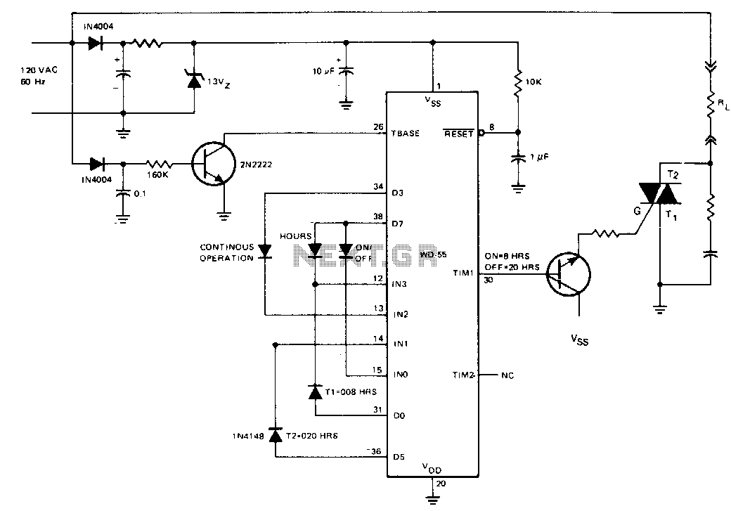
The AC line-operated on/off controller is a straightforward and dependable solid-state alternative to a motor-driven cam switch. Time intervals 1 and 2 are programmed using diodes to be 8 hours and 20 hours, respectively. The TIM1 output is buffered...
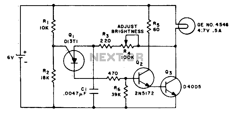
This circuit alters the average value of the DC supply voltage due to the high switching frequency. The tungsten lamp will exhibit an almost continuous adjustable light output ranging from 0 to 100%. If a light-emitting diode is utilized...
S1 and S2 are normally open, push-to-close, momentary switches. The diodes, which can be either red or green, serve solely to indicate the direction of operation. The TIP31 transistors may need to be adjusted based on the specifications of...
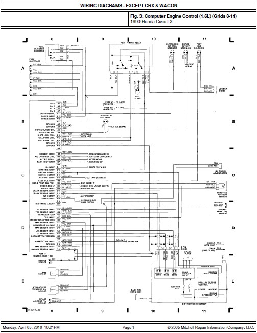
This document contains the wiring diagram for the 1990 Honda Civic LX. It includes diagrams for the Computer Engine Control (1.6L) located in grids 8-11, the Steering Column and A/C Heat systems in grids 20-23, as well as the...
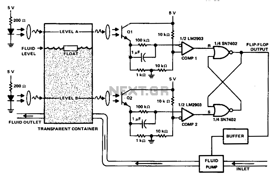
This circuit can be used to maintain fluid between two levels. Variations on this control circuit can be made to keep something that moves within certain boundary conditions. The described circuit functions primarily as a fluid level control system, designed...
The ATA5423, ATA5425, ATA5428, and ATA5429 are highly integrated UHF ASK/FSK multi-channel half-duplex transceivers characterized by low power consumption. These devices are housed in a compact 7 x 7 mm QFN48 package. The receiving section features a fully integrated...