
VCR Video Detector Switch Controller Circuit

This circuit functions as a video detector switch controller, designed to manage the video output from a VCR (Video Cassette Recorder) or a camera. The primary objective of this circuit is to detect the presence of a video signal and switch the output accordingly. It is particularly useful in applications where automated switching between multiple video sources is required.
The core components of the circuit typically include a video signal input, a detection circuit, and a switching mechanism. The video signal input receives the output from the VCR or camera, which is then processed by the detection circuit. This detection circuit usually employs a comparator or an operational amplifier configured to monitor the amplitude of the incoming video signal. When a valid video signal is detected, the circuit triggers the switching mechanism.
The switching mechanism can be implemented using either a relay or a solid-state switch, depending on the desired application and load requirements. A relay provides physical isolation and can handle higher power levels, while a solid-state switch offers faster switching times and increased reliability due to the absence of moving parts.
Additional features may include indicators such as LEDs to show the status of the detected video signal and the active output. The circuit may also incorporate a delay timer to prevent false triggering from transient signals or noise. Proper power supply decoupling and filtering are essential to ensure stable operation, particularly in environments with electrical noise.
Overall, this video detector switch controller circuit offers a practical solution for managing video inputs in various electronic applications, enhancing automation and user convenience.VCR Camera Video Detector Switch Controller Circuit This video detector switch controller circuit uses the video output from a VCR or camera to.. 🔗 External reference
Related Circuits
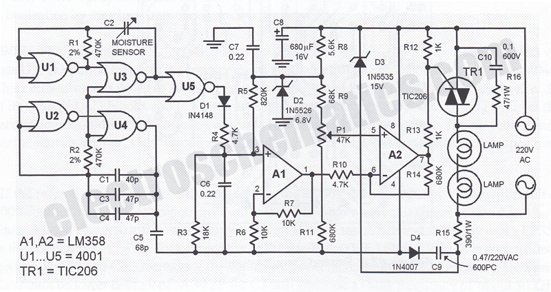
This humidity-controlled switch circuit activates and deactivates an electrical load, such as a heater, based on the moisture content in the surrounding air. The humidity-controlled switch circuit employs a humidity sensor to detect changes in moisture levels in the environment....
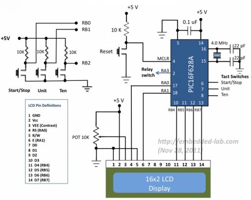
A source code for a simple PIC-based digital timer is provided. The hardware for the project is not available; however, it will be demonstrated using a DIY PIC16F628A breadboard module and I/O board. The complete circuit diagram and firmware...
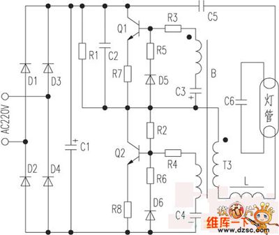
The saving lamp circuit features two main types: glass cover and exposed. The glass cover variants include three series: spherical, cylindrical, and processing types. The first two series consist of four variations: transparent, carved, engraved, and white. These lamps...
The objective is to enhance information transmission through the use of articles. Please contact us via email at [email protected] within 15 days if there are any issues related to article content, copyright, or other concerns. Prompt action will be...
Developed as an interface between the General Instruments AY-3-8500-1 TV game chip and the antenna terminal of a TV set. Adjust capacitor C1 to the frequency of an unused channel to which the receiver is set for playing games....

In some buildings, there is a need for effective security measures. An example of this is the door knock alarm, which is a simple design intended for basic home security. This circuit utilizes a piezoelectric sensor to detect knocking...